In-Depth Look at Structural Checks in PLS-CADD
By Paul Richardson - Director of Engineering at NM Group
In my latest In-Depth Look article, I wanted to go through how to run structural checks in PLS-CADD. Why would you want to do this? Well, a Structure would normally be designed to withstand the loads (wind and Ice) for a certain Conductor System, Span, configuration and location. What if that configuration changes, or the Conductor System? In that instance, the Engineer needs to verify that the structure is capable of withstanding the applied loadings for that revised arrangement.
Previously this would have been performed using Statics or in the case of an indeterminate structure force diagrams or method of sections. Clearly then, things have moved on and PLS-CADD provides a powerful toolset to help us query structural issues and determine the integrity of a tower. PLS CADD can also consider the effects of deflection and node displacements and perform a full non-linear structural assessment, very important when considering guyed or slender structures.
Structural Checks in PLS CADD
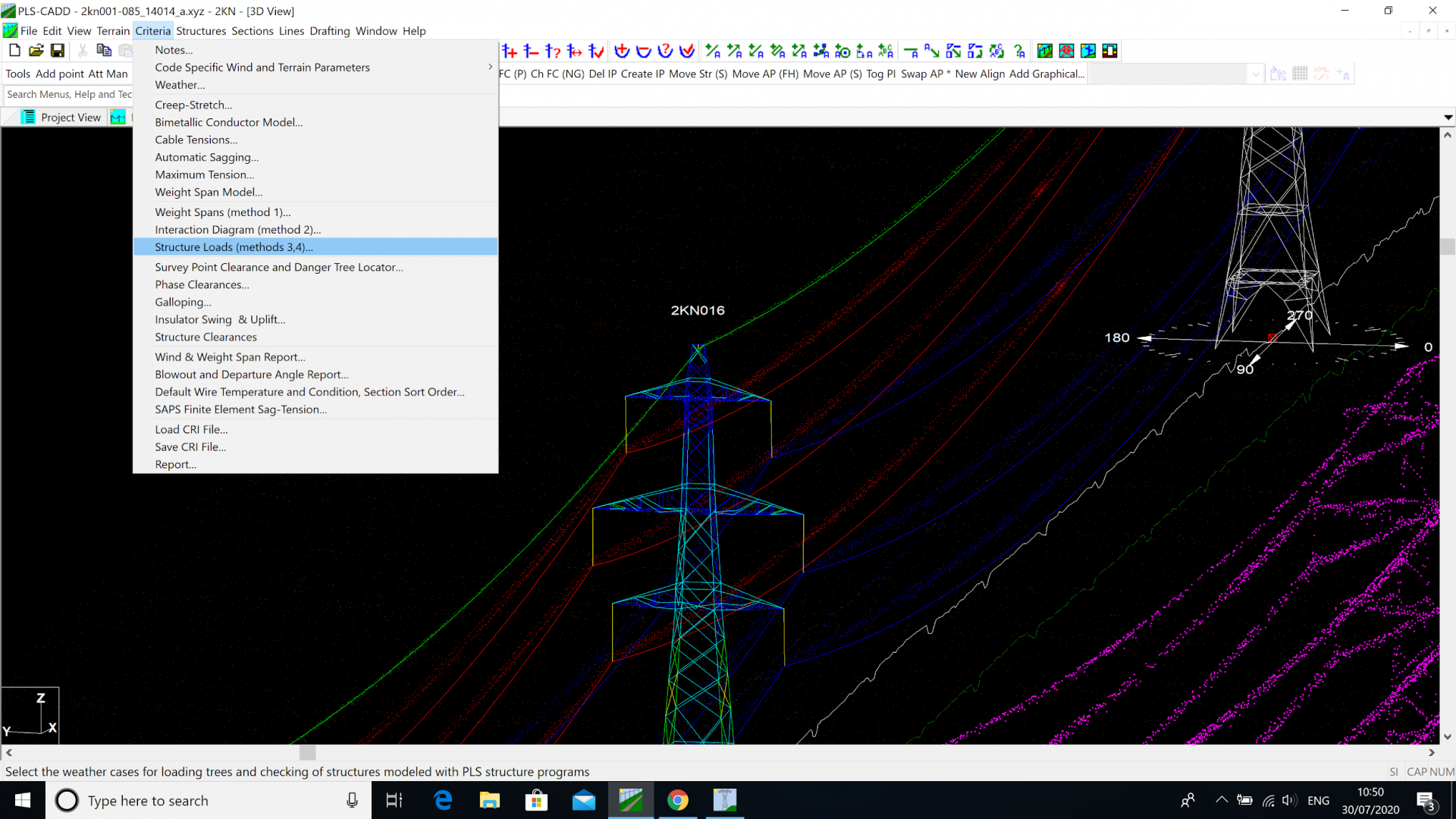
To enable Structural Loading checks in PLS CADD we need to add the specific checks to Criteria - Structure Loads (Methods 3 and 4).
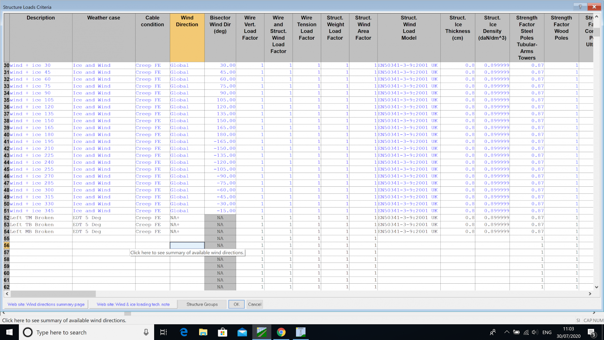
That will open up the following Table where we can add in Loading Checks; Climatic Loads, for example, such as a Heavy Ice check, a High Wind check (at a given angle of wind direction) and a Wind on Ice check (again at a given angle of wind direction). We can also add in Broken Wire checks and variations thereof, where any combination of Phases and Earthwires can be simulated as Broken, either in the back, ahead spans or both.
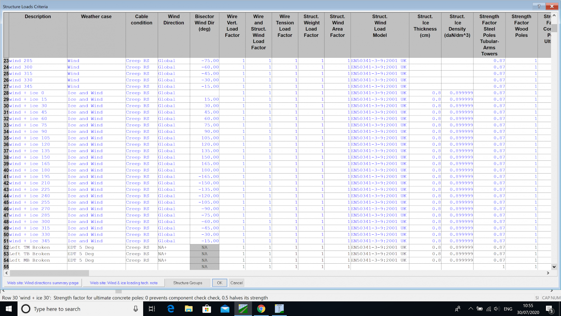
In the Table, we can see several Climatic Loading checks and also three checks on ‘Broken Wire’ in this case simulating the effect of breaking the Top and Middle, the Top and Bottom and the Middle and Bottom phases in turn.
To visualise these broken wire conditions within PLS CADD we must select Load Case Display in our ‘Display Weather Case’ dialogue.
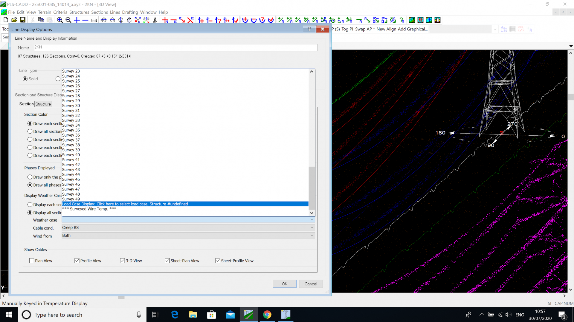
However, when I select the Load Case I wish to display I get a blank selection screen.

As this feature allows you to see the impacts of non-uniform loading it can only be activated in Finite Element mode. Therefore we need to go back to Criteria - Structure Loads and change the Creep RS load case to Creep FE.
Sections - Display Options now allows me to select a Load Case and a Structure at which that load case is applied.
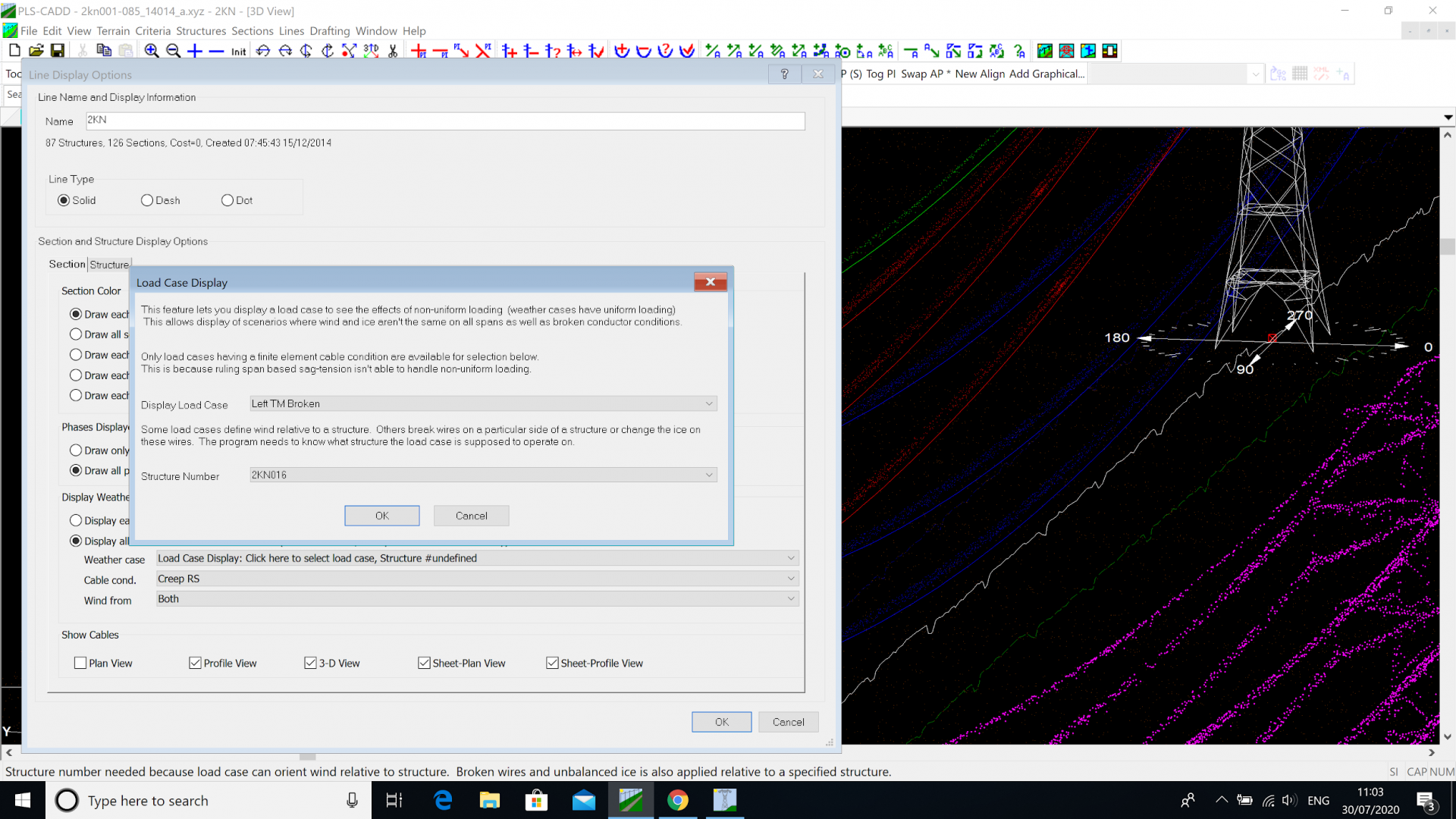
In this case Left TM Broken (Top and Middle phases broken on the Left Circuit) and Structure 16. We can now display the impact of Breaking the phase conductors on the Top and Middle phases.
However we have activated SAPS (putting ourselves into Finite Element mode rather than Ruling Span) but only Level 2, where no deflection of the structure is considered (only the Suspension Insulators).
If I were to go to my SAPS Options I could activate SAPS Level 3 or 4. (More info on that in the discussion on Levels of SAPS).
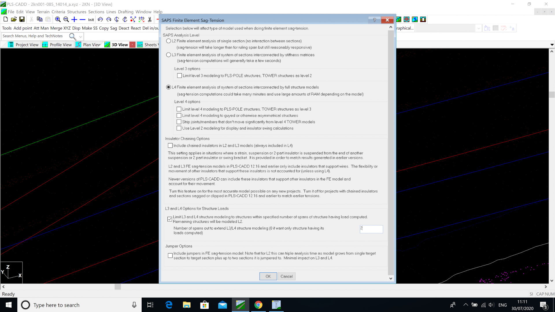
Level 4 can take an outrageous amount of time, and for lattice towers gives little benefit over Level 3. (For poles the difference can be quite noticeable, for lattice structures quite negligible).
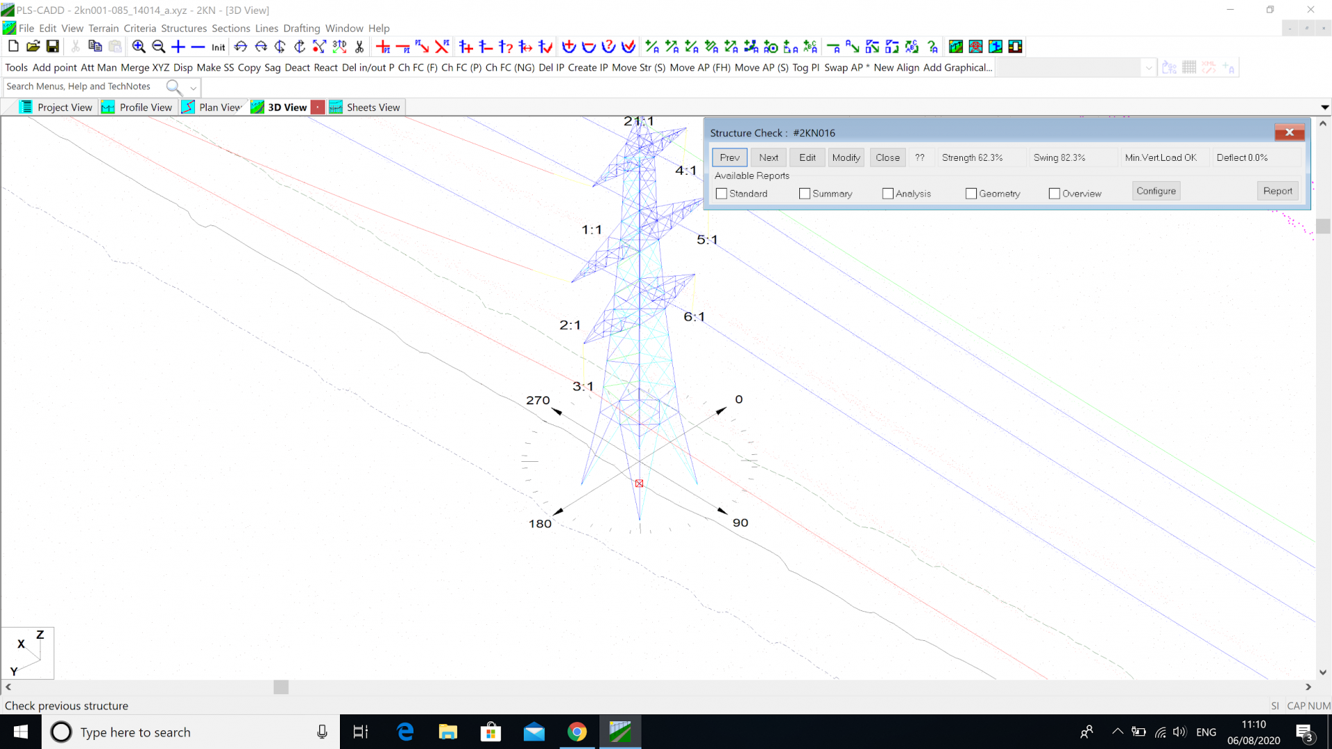
The Level 3 Analysis is shown below.
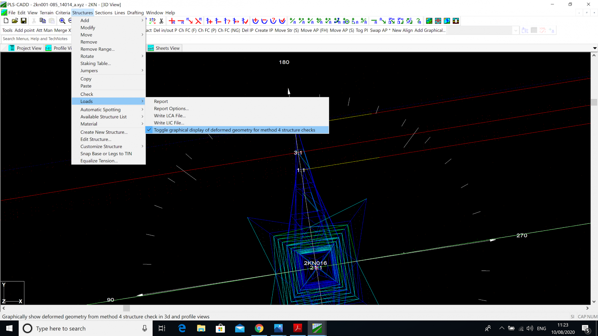
Finally now the Level 4 analysis. It is necessary to activate ‘Structures - Loads - toggle graphical display of deformed geometry for method 4 structure checks’.
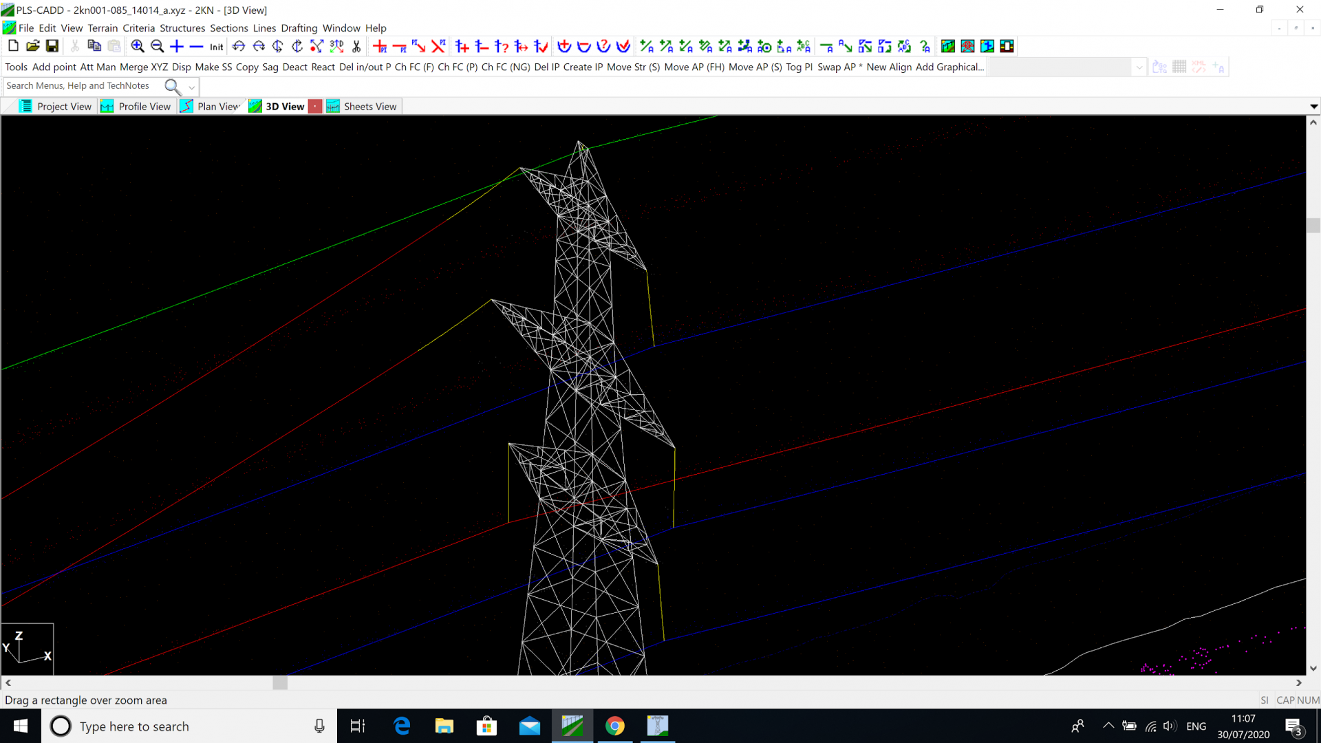
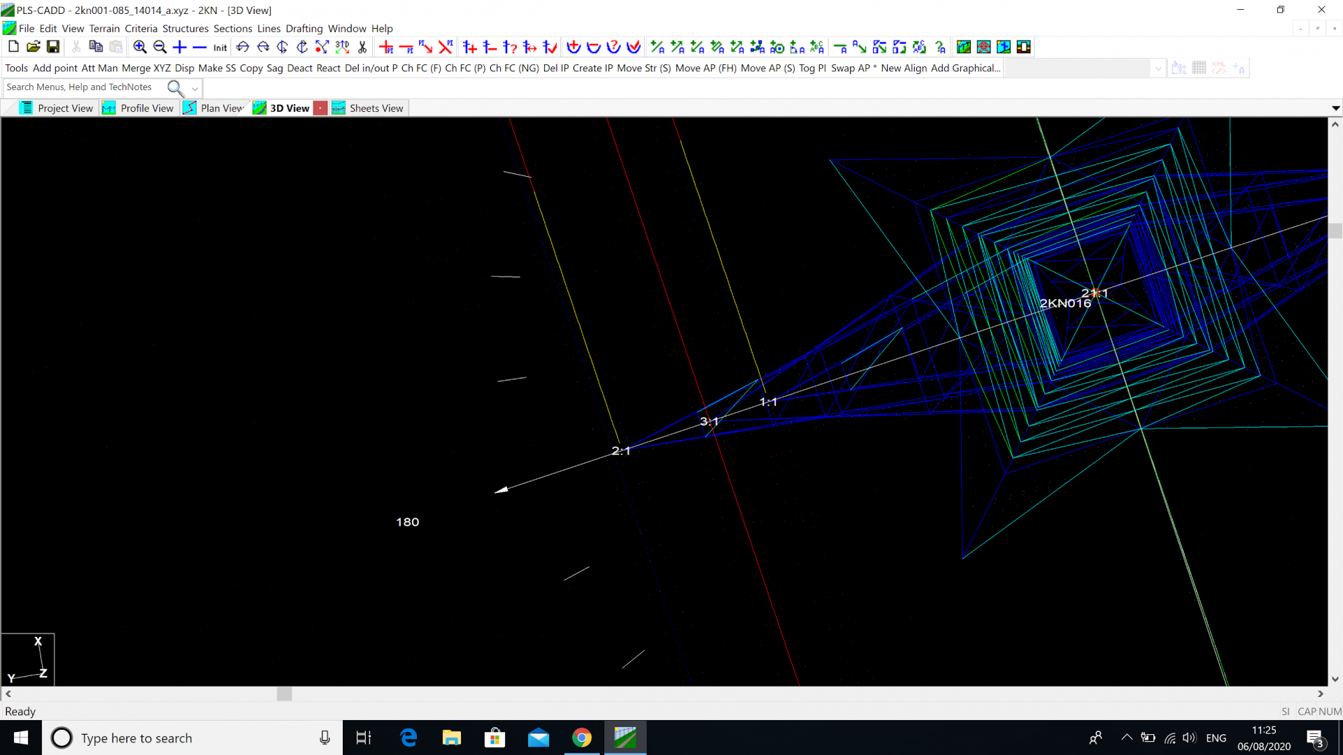
The deformed geometry looks like this:
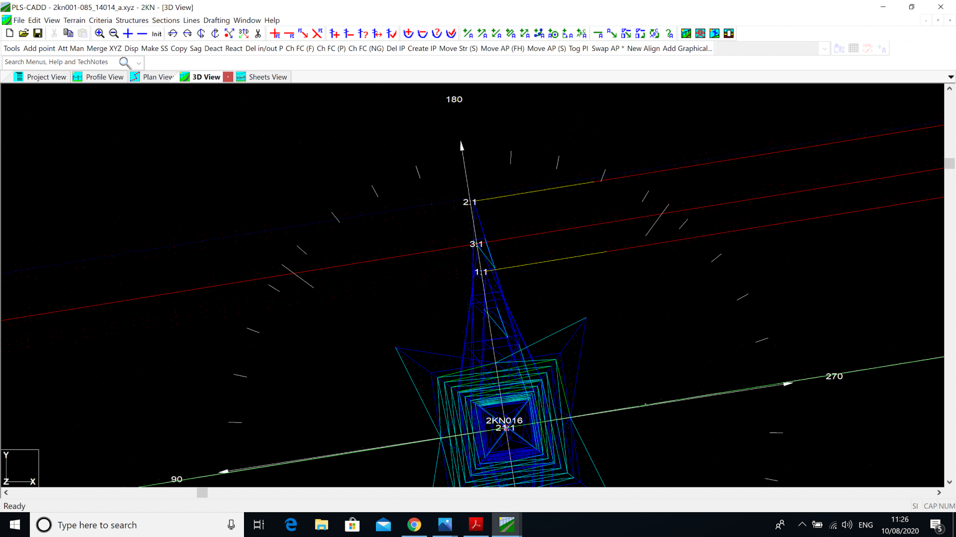
Where the deflected shape of the structure is more noticeable when we zoom right in.
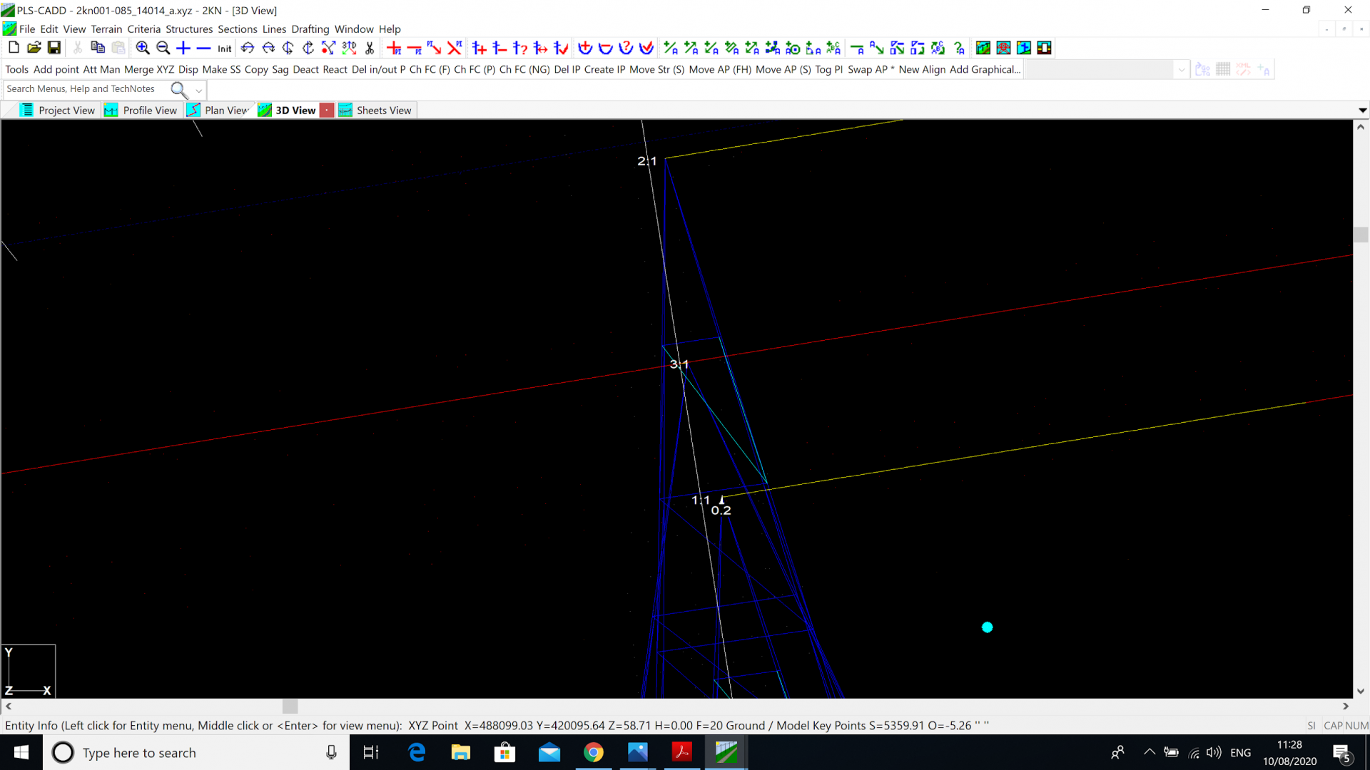
We can see that the top and middle crossarms both deflect by around 200mm under the ‘broken wire’ condition.
So as we have seen PLS CADD, Pole and Tower give opportunities to understand Structural Capacities and give the Engineer the possibility to assess the strength of Towers and Poles under a number of different analysis modes. We have outlined why the Engineer may choose a certain analysis for one structure while that may not be appropriate for another structure or application.
I hope this blog has proven useful and, as always, feel free to get in contact if you have any comments.
As Director of Engineering and heading up research and development at NM Group, Paul Richardson is a renowned power industry expert and long-time proponent of the use of 3D modelling in improving reliability and utilisation, while minimising cost. He is a chartered civil engineer (BEng Hons, CEng, MICE), and retains a wealth of experience, including 30 years of power line engineering.