Ask an Engineer Part 6 - L1, L2, L3 and L4 conductor systems
How can we remember the complicated terminology associated with PLS CADD, such as L1, L2, L3 and L4 conductor systems?
If you’re an old hand at the software, these definitions will be absolutely clear to you and won’t require and explanation, if you are relatively new to the software, my advice is to not use them. Completely ignore the fact that L1 through 4 or M1 through 4 exist.
Don’t call them by the abbreviations, which may lead to misunderstanding. Call them by the purpose of the structure model or analysis that you are performing. That way you can avoid misunderstanding, and you will find that really soon all those weird L1’s and M4’s will stop being an arcane pursuit and become a convenient shorthand for something very meaningful.
We looked at Structure Methods in the last ‘Ask an Engineer’ so now we are going to look at the different ways the ‘conductor system’ can be modeled. First up, what is a ‘conductor system’?
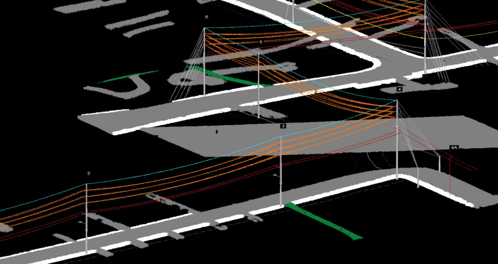
A conductor system describes all of the components which may define the behavior of a conductor. This might include lattice towers, pole structures, insulators, conductors, marker balls, applied loads etc..
Before we start, let’s discuss some terminology regarding sag – tension behavior.
Span Length
The span length is the horizontal (2D) distance between the center of one structure to the center of the next structure. The structure span length can be different from the circuit span lengths and the ‘inclined span length’.
Inclined Span Length
Is the true (3D) distance between the center of one structure to the center of the next structure.
Tension Section
A tension section is defined as the distance between dead ends, this should be similar to the sum of the span lengths in between dead end structures.
Ruling or Equivalent Span
A mathematical representation of a weighted average. Thus:
RS = SQRT( {S14/C1 + S24/C2 + . . + Sn4/Cn} / {C1 + C2 + . + Cn} )
Where Si = Horizontal (2D) Projection or Span Length, and Ci = True (3D) or Inclined Span Length.
What do we mean by a ruling span or equivalent span analysis?
Let’s take a look at an equivalent span, or ruling span model. We can open up the demo.xyz file which ships with the software. When we go to 'sections - table' we see the following.
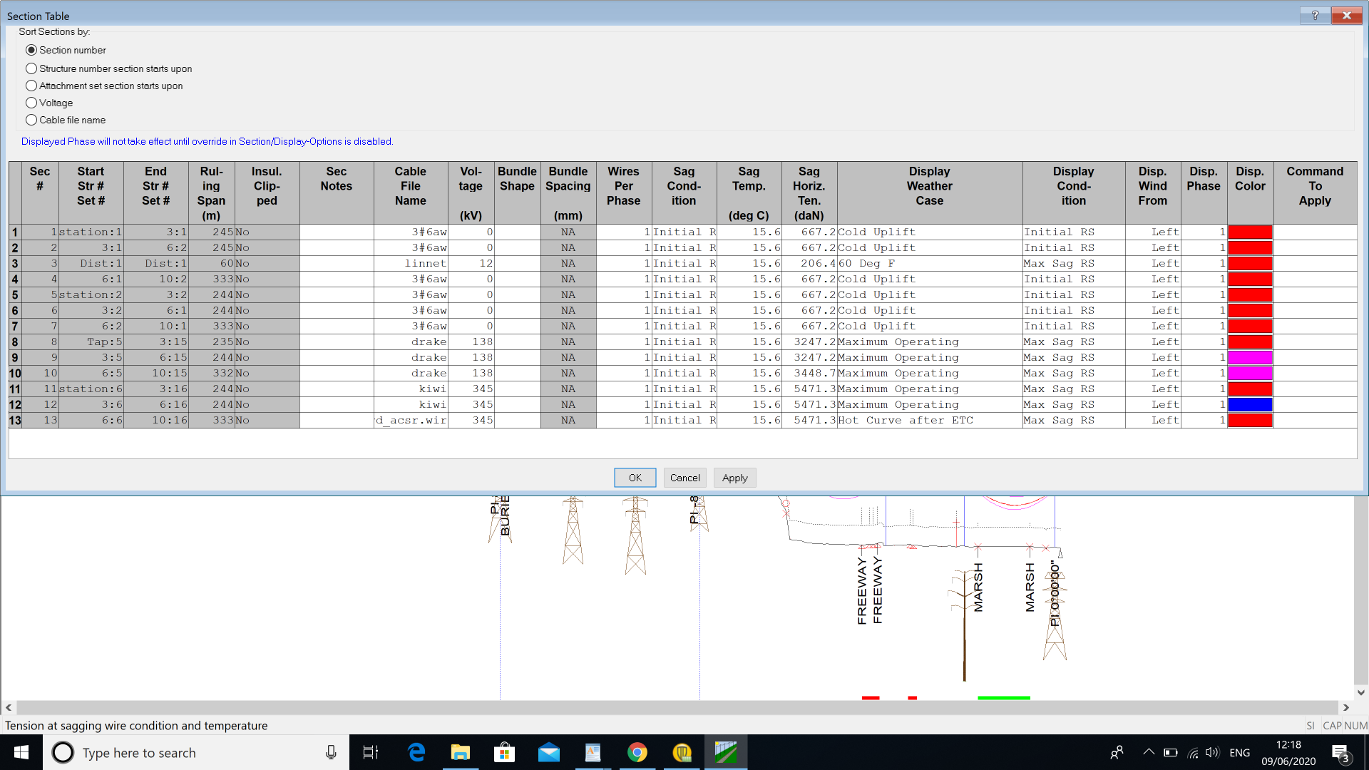
The display condition is shown as Initial or Max Sag RS, RS stands for Ruling Span.
That means that the sag - tension behavior is defined by the 'ruling span approximation'. This is also known as Level 1 Analysis. Level 2, Level 3 and Level 4 Analysis are more refined methods of determining sag - tension, but which of these analyzes is appropriate for your particular application?
SAPS - Finite Element Sag - Tension
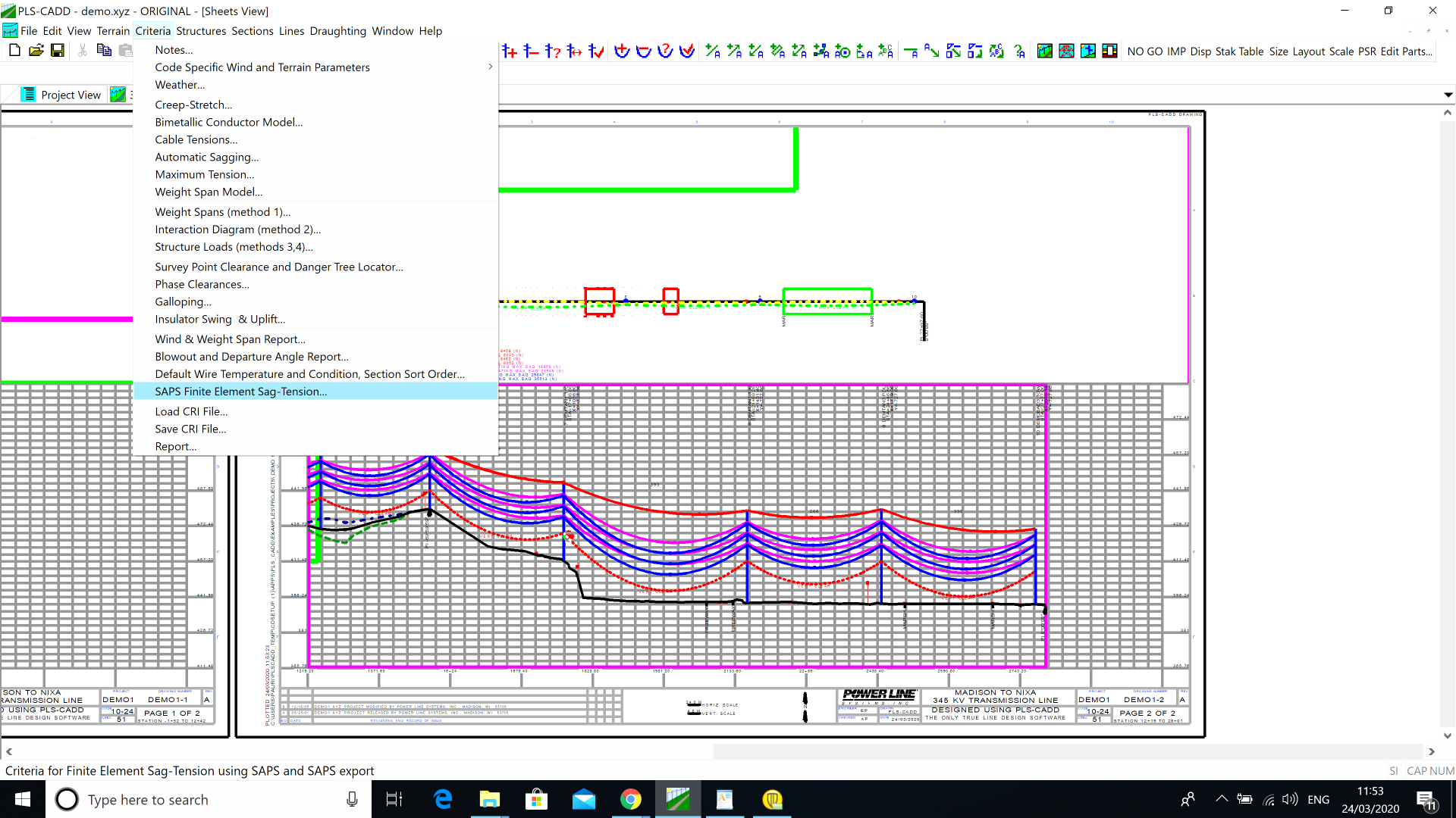
Ruling Span Mode - L1
There is a command called SAPS Finite Element Sag - Tension, this will only be accessible if you have the SAPS option. If you do not have SAPS all of your engineering studies and analysis will be performed in Ruling Span (sometimes called Equivalent Span) mode, or in SAPS terminology Level 1. In this case the tension remains the same throughout the tension section, however there is no interaction between tension sections. This means that Dead End attachment points are considered to be fixed and will not move, so there is no flexibility considered for any of the structures. As the tension in all parts of the tension section remain equal, there will be no differential tension on either side of a suspension insulator and hence no insulator swing.
Power Line Systems consider that this Ruling Span approach is suitable for the vast majority of Engineering applications. I have to disagree and say that L2 (which we will describe in more detail later, is more appropriate for the vast majority of Engineering applications. (Unless you live in Oklahoma, or similar, in which case L1 is absolutely fine. Again more on the reason for that later.)
Full interaction of all wires and structures - L4
Level 4 - Full interaction of all components within a single structural model including all structures and wires. Is this appropriate?
The most advanced modeling level (Level 4) is based on a full structural analysis of the entire tension section, including detailed models of all supporting structures and all cables. Because it is computer time intensive and is not justified in most situations, Level 4 should only be used in special cases where a very accurate representation of the interaction between the structures and the wires needs to be considered. You may never have the need for this advanced modeling capability (Level 4). Between Level 1 and Level 4, there are two intermediate modeling levels (Level 2 and Level 3).
Level 2 - Finite Element Modeling ignoring the interaction between wires.
In this method all supports are considered infinitely rigid unless you choose to add fictitious springs (which will require a M4 Full Structural Model.)
The method also ignores any interactions between wires, whether those wires be adjacent tension sections or other phases on the same tension section. This method allows for differential tensions within 'tension sections'. A 'tension section' is only ever equal at one condition (most likely the condition at which the wire was installed) any changes to conductor temperature and creep will cause different amounts of 'slack' in each span, that 'slack' will vary the tension within that span, most noticeable when the suspension insulators appear inclined, and the sags will vary.
This is particularly problematic in the case of long span / short span interaction. As a person that has seen thousands of miles of LiDAR data, and has first used RS to approximate the sagging conditions and then used Finite Element to match the 'as installed' behavior of the conductor, I can say that very few lines can be accurately represented using the Ruling Span approach.
Level 3 - Finite Element Modeling accounting for interaction between wires
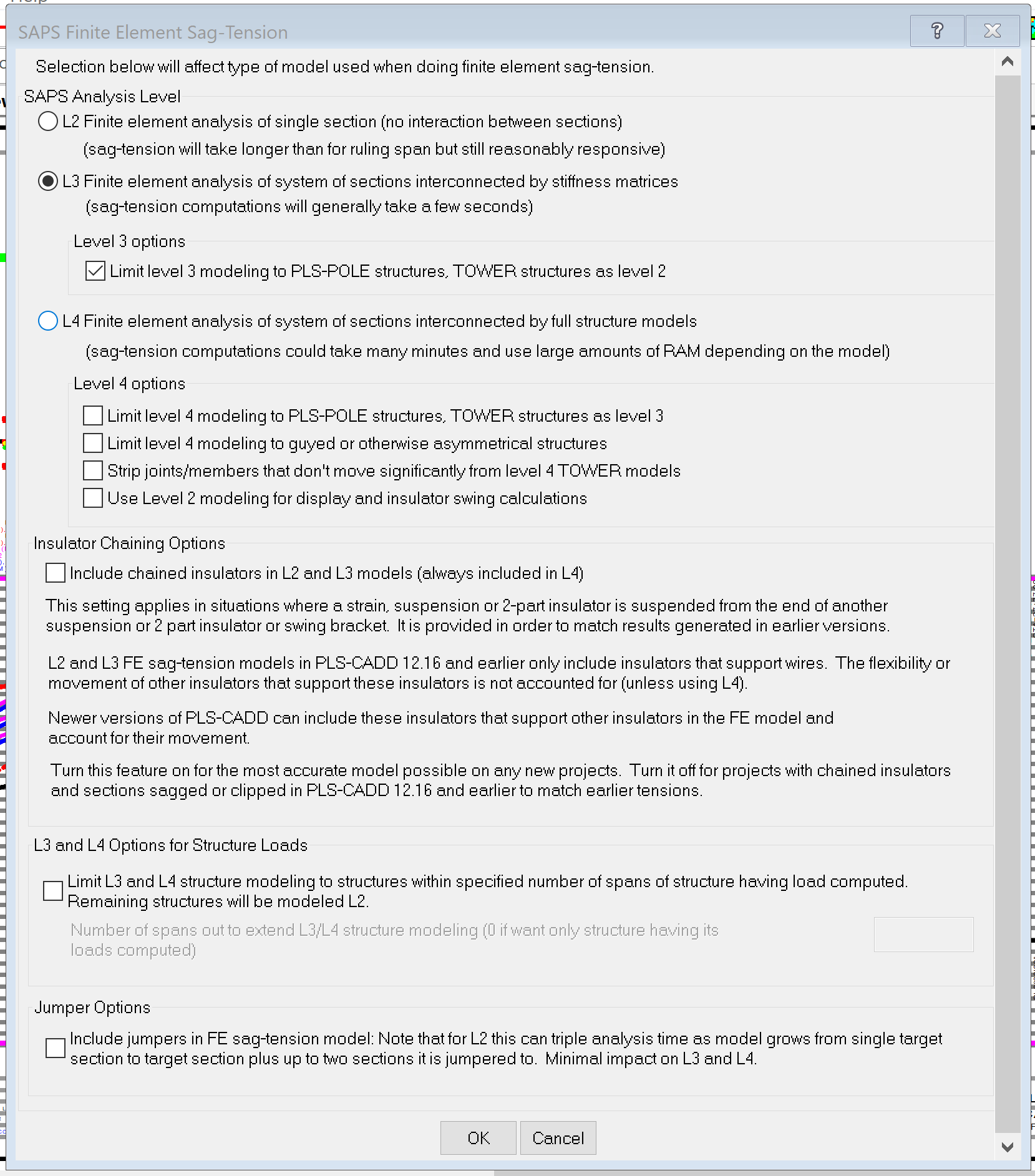
This method is similar (particularly in result) to Level 4, but is computationally quicker as the method uses a simplified stiffness matrix, created when each Method 4 structure is analyzed, negating the need for iterations of Full Structural Analysis while the full L4 model seeks to converge.
In my opinion, if you are using slender structures which are likely to deflect, or guyed structures, or are trying to mimic the effect of stringing operations I would recommend using Level 3, for all other situations a L2 analysis is sufficient.
A good compromise between these two positions can be found below, where all PLS Pole structures are analyzed using L3 while all Tower models are analyzed using L2. Also, when calculating structural loadings at a particular site there is an option to limit enhanced L3 / L4 analysis to structures a certain number of spans away form the structure being analyzed.
Conclusion
PLS-CADD allows a number of options to be used to define structure strength. These options are best referred to as ‘allowable spans’, ‘interaction diagrams’ or ‘full structural model’. The selection of which structure method is best for your application will depend on the information you have available. It should be noted that ‘Full structural models’ cannot be used directly for ‘Tower Spotting’ but they can be converted into ‘Allowable Spans’ or ‘Interaction Diagram’ models which can then be used in Tower Spotting.
About the Author
As Director of Engineering and heading up research and development at NM Group, Paul Richardson is a renowned power industry expert and long-time proponent of the use of 3D modeling in improving reliability and utilization, while minimizing cost. He is a chartered civil engineer (BEng Hons, CEng, MICE), and retains a wealth of experience, including more than 30 years of power line engineering.