An in-depth look at modelling jumpers in PLS-CADD
By Paul Richardson - Director of Engineering at NM Group
In a recent article I looked at the difficulties and inherent issues in modelling jumpers on transmission and distribution networks. I also discussed that PLS-CADD™ were looking at how to incorporate more accurate jumper modelling in future versions.
I am pleased to say that this capability is now available in the latest update of PLS-CADD™ (v14.50). As the subject got a lot of interest previously I wanted to follow up and look at how this new functionality actually works in practice.
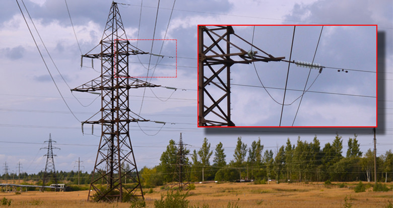
To do this lets first consider two powerlines, a 110kV line and an 11kV line. This provides our transmission and distribution case respectively. For the purpose of this example, the main difference between the two lines is that the 110kV line can be considered to be flexible and the jumpers hang vertically down below the insulators. Whereas for the 11kV line, the jumpers are considered to be rigid and loop over the top of the connecting strain insulators.
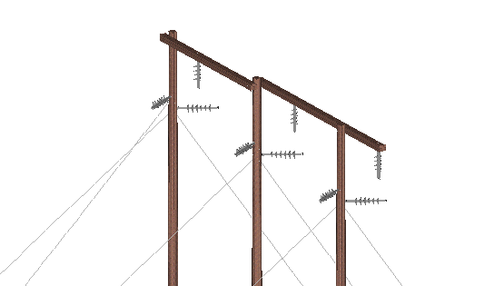
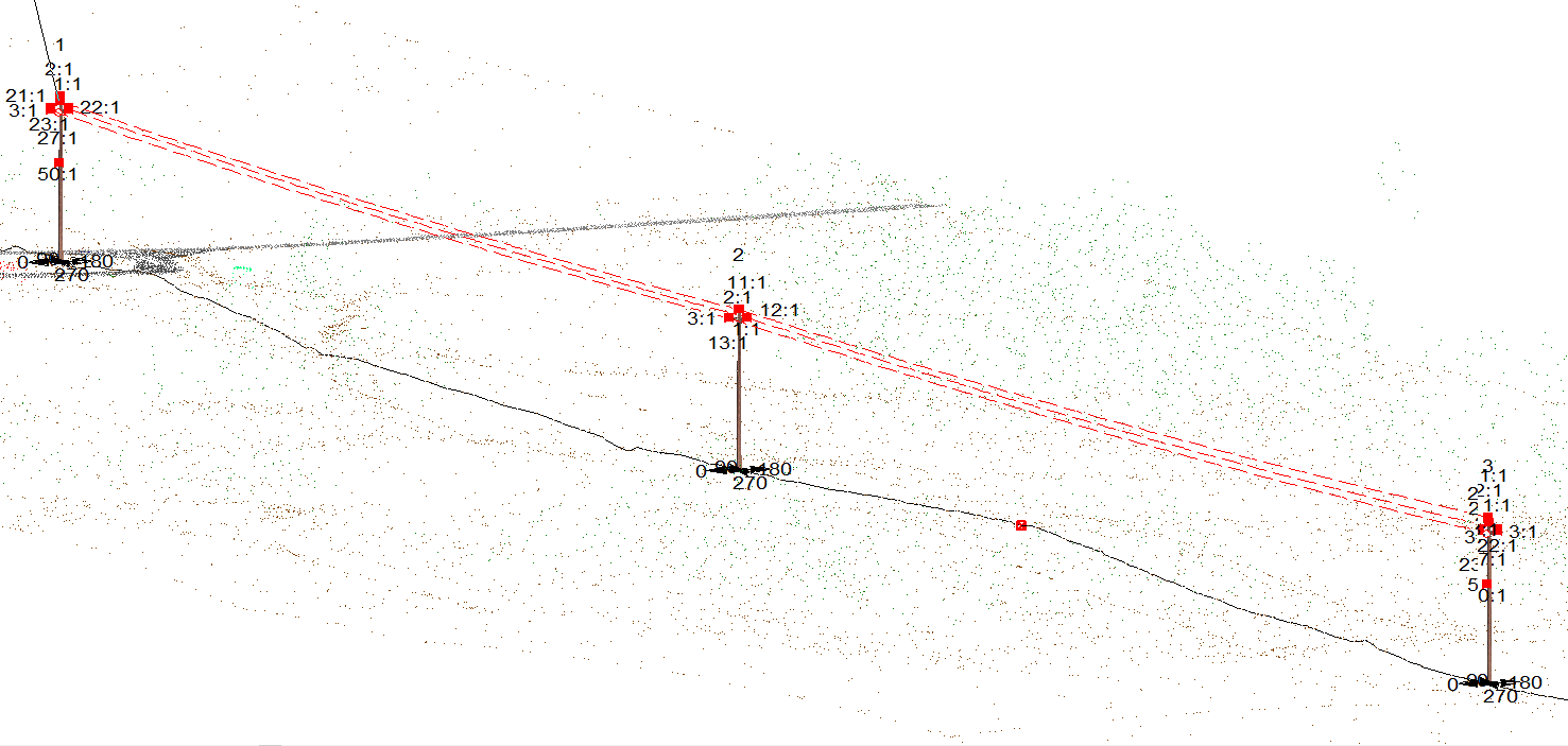
Let’s start by looking at the 110kV model. Three structures are placed on an alignment.
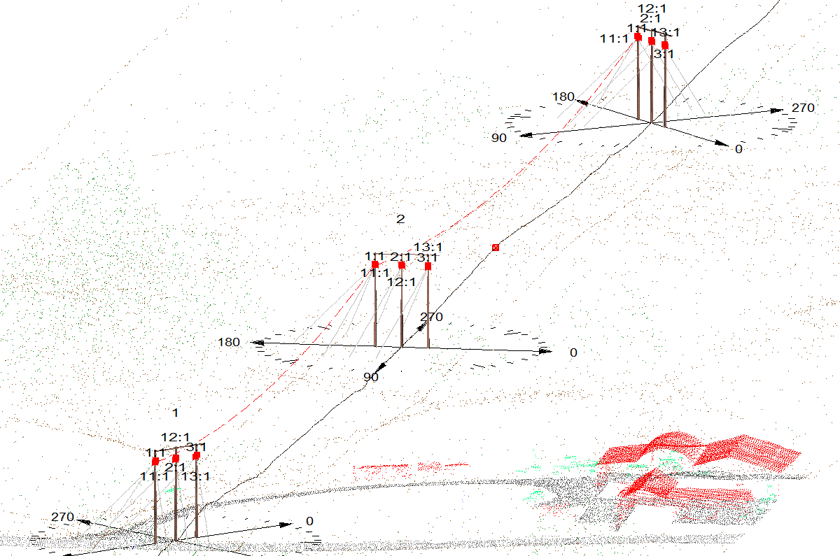
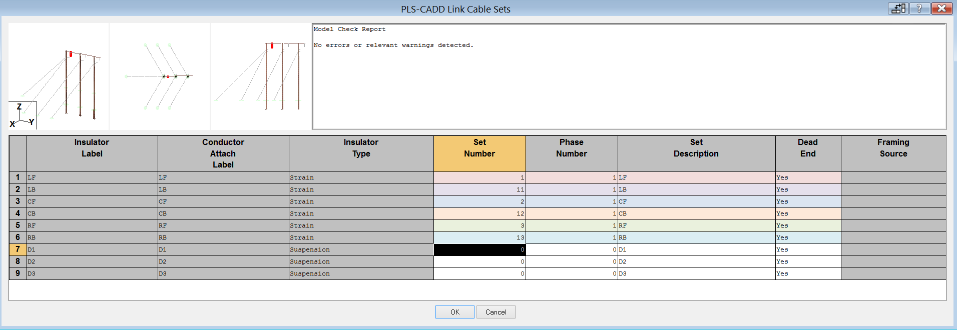
I have strung the two adjacent sections from set no. 11 to set no. 1
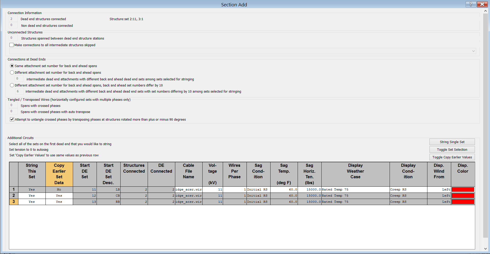
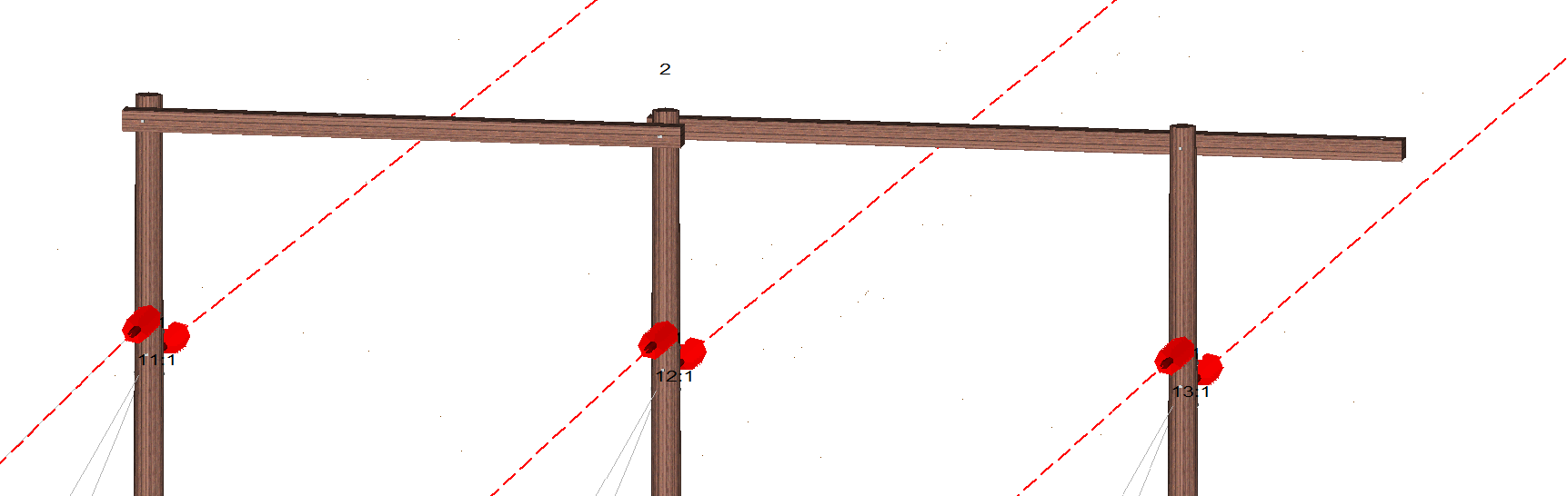
The convention will be followed by PLS-CADD stringing the other phases from 12 to 2 and from 13 to 3. The conductor is Partridge and is strung at a tension of 15000 # (Lbs). The enlarged detail of structure 2 shows that the back span(s) terminate(s) on 11,12 and 13; the ahead spans start of 1,2 and 3.
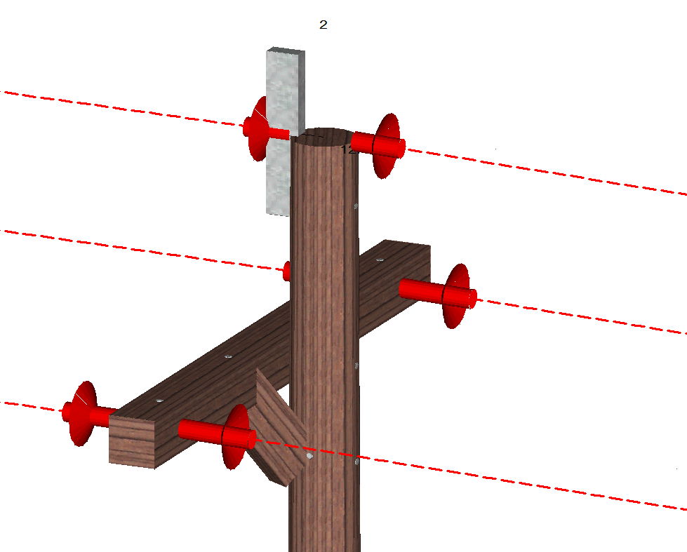
You may notice that PLS CADD does not show any pilot/stand-off/idler strings (delete as applicable!!). If you edit that structure in PLS Pole however, you will see this:
The insulators are only shown in PLS-CADD if they have conductors attached to them. Also, within PLS Pole, we can see that the PLS-CADD insulator link unit has not been used to assign set and phase for each idler string.
I’m going to make these idler strings set numbers 21,22 and 23. Each will be assigned Phase 1.
Now, within PLS CADD, we can see the following:
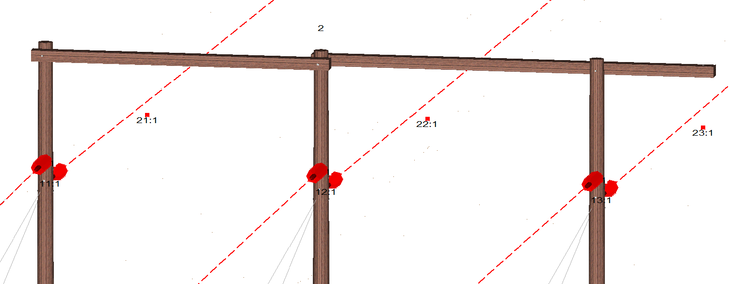
If the set and phase numbers don’t show up, go to ‘Drafting>Show Set and Phase Labels in 3D Views’ and ‘Drafting>Show Cable Attachment Points’ and you should see similar to the above. (If you still don’t see the numbers, check once again that the set and phase labels are assigned in ‘PLS CADD Insulator Link’.)
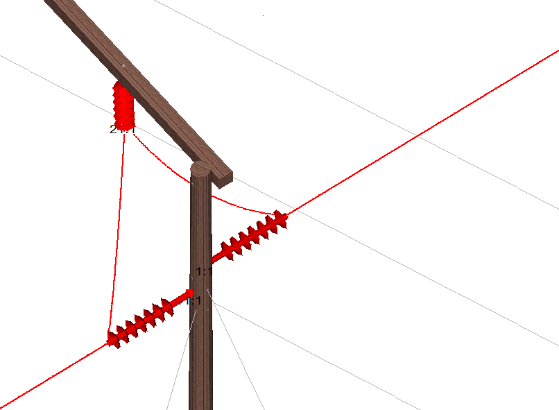
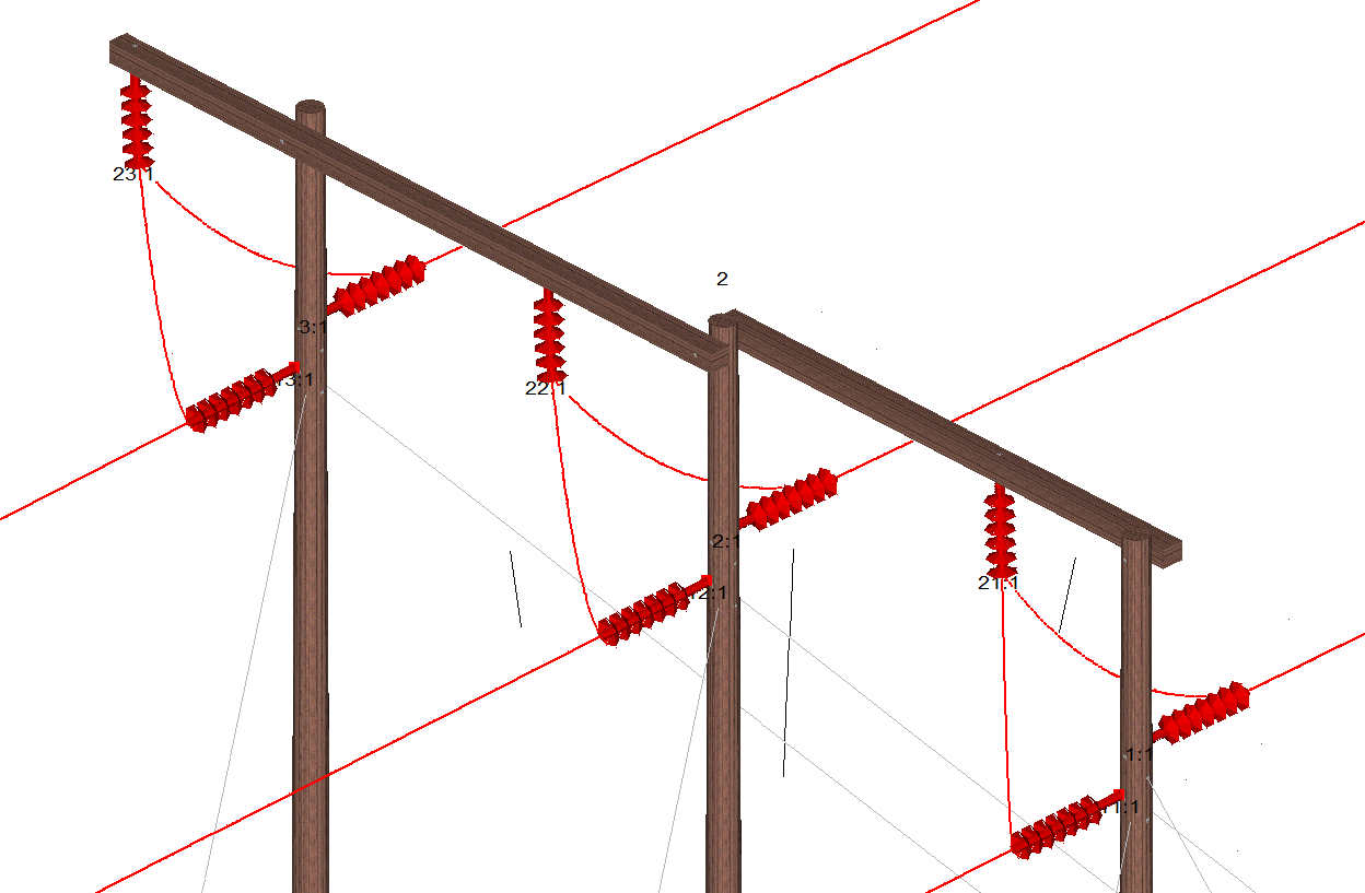
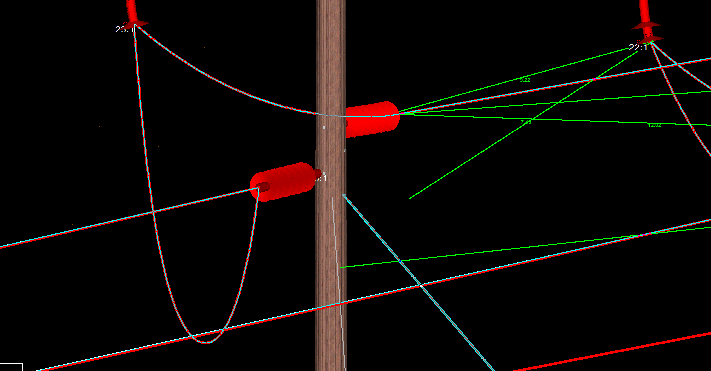
I am going to attempt to string a jumper between set 11, set 21 and set 1. To do this I go to ‘Structure Modify’ and select the ‘Jumpers’ button on the dialogue box. I enter the connection points and the sag of each jumper and I get the following:
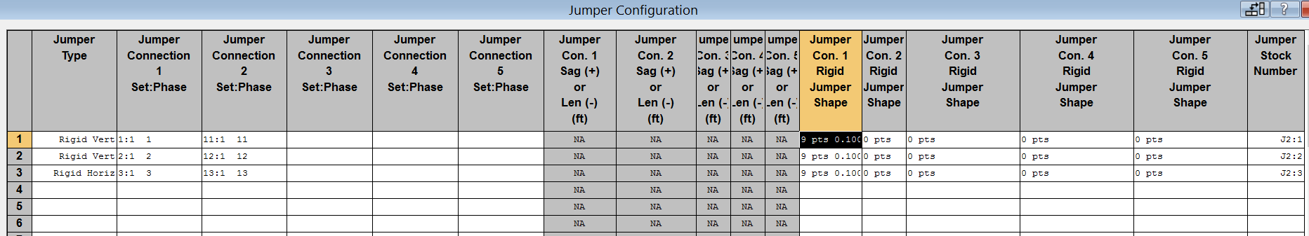
Let’s look at the table in more detail and see how I should connect the remaining jumpers.
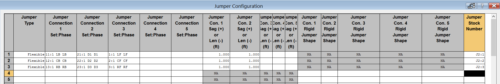
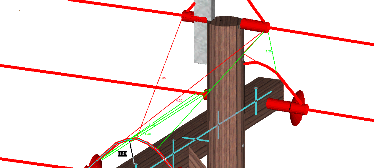
If desired, stock numbers for each jumper can be added, in which case they will be recorded in the structure and line material lists. The structure now looks like this:
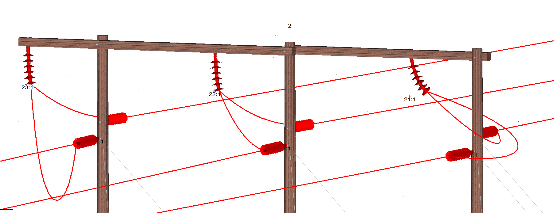
The loads (wind / wind on ice / ice) for the jumpers WILL BE INCLUDED IN THE FINITE ELEMENT ANALYSIS for the structure. The effect of this can be seen if we make some of the jumper sags artificially small or large.
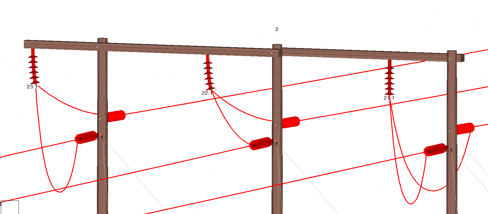
It is possible to change the weather case chosen for the ‘display condition’, for example a ‘blow out condition’ may be applied. In this case I only changed the RH set for the ‘blow out’ case.
As the jumper is considered part of the ‘wire system’ it is possible to check clearances: to ground, to structure, between sections (at various weather cases) or between galloping ellipses.
Now let’s look at the 11kV example. Let’s put three poles on a simple alignment.
We can now add jumpers to this structure, however in this case there are no Idler insulators.
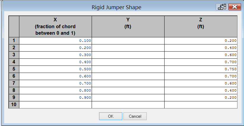
Each rigid jumper shape is defined like this:
And the connections are defined like this:
Now the jumpers are not part of the FE model and cannot be displayed for other weather cases (as they are considered rigid). The loads imparted on them can be calculated and transferred to the structure programmes (PLS Tower or Pole); also clearances to ground, to structure and between clearances or galloping ellipses can be calculated in PLS CADD.
Adding this functionality to PLS-CADD™ helps to deliver a more accurate assessment when modelling and considering the effect of jumpers on OHL design. This means that you can now more accurately consider the effect of jumpers on internal clearances and determine if the jumper is a constraint for external clearances.
I hope this blog has proven useful and, as always, feel free to get in contact if you have any comments.
As Director of Engineering and heading up research and development at NM Group, Paul Richardson is a renowned power industry expert and long-time proponent of the use of 3D modelling in improving reliability and utilisation, while minimising cost. He is a chartered civil engineer (BEng Hons, CEng, MICE), and retains a wealth of experience, including more than 20 years of power line engineering.