An in-depth guide to modelling downleads in PLS-CADD - Part 1 getting the geometry right
Over the course of a few blogs, I wanted to look at the process of modelling ‘downleads’ in PLS CADD. This topic gets a lot of interest from clients so I think it is worthy of some attention. Part of what makes it so complex is that traditional concepts such as sag have no value and tensions become very important and are incredibly sensitive to changes in span length.
Before we start though we need to talk about some of the concepts involved in downlead modelling. This is important to establish regardless of any modelling software discussions. Then we can look at modelling geometry in PLS-CADD.
Important terminology?
So let’s start with the most important question ‘What is a downlead?’
A downlead is typically the connection between an Overhead Line ‘Terminal Structure’ and the adjacent Substation equipment. The physical connection for the downlead is likely to be to a Substation Line Landing Gantry or vertically down to Anchor Blocks or a Sealing End Compound or Platform. The electrical connection is likely to be via a ‘downdropper’ (analogous to a jumper on a strain structure) providing electrical continuity.
Why are downleads considered differently and how does a downlead differ from a normal transmission line span?
Well for a start, tensions are typically much lower than those of a typical transmission span. The span lengths are also normally considerably lower than a standard span. In addition, because of the geometry associated with downlead connections, defining sag – tension behaviour by a ‘sag’ at a given temperature becomes much more difficult, defining sag-tension behaviour by tension becomes more appropriate.
What are examples of typical downlead arrangements, and what are the challenges therein?
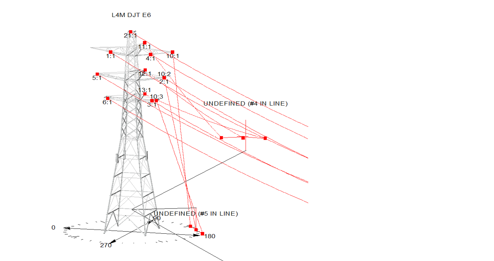
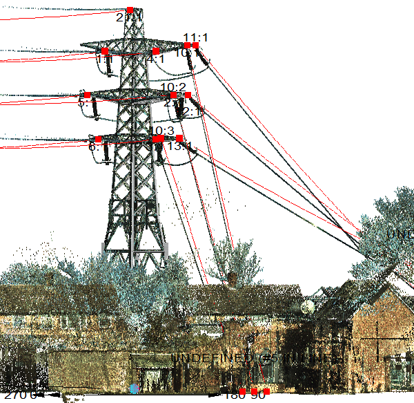
Below we can see both types of downlead arrangement; Terminal to Gantry (typically horizontal, terminating onto a Line Landing Structure) and Terminal to Anchor Blocks (typically vertical, terminating onto ground or onto a Sealing End Platform).
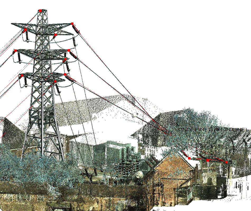
The tensions used to model these downleads will vary significantly from each other and vary significantly from tensions typical for a normal transmission span.
Modelling an existing downlead arrangement.
To model these downleads the first requirement is to accurately model the geometry of the downlead attachment points. I am going to start by modelling the anchor block attachments, or the points at which the insulated downlead staywire attaches to the ground.
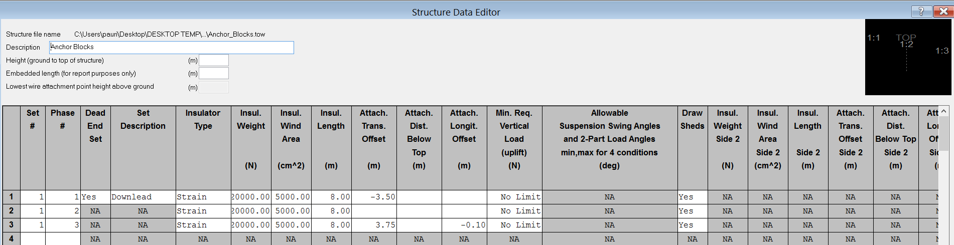
I have modelled all three phases as a single set, on a single structure.
So, the steps are; create a structure with the approximate geometry. Add a PI for the Anchor Block location, Place the structure at the appropriate location, use the site specific ‘modify attachment point’ tool to get the geometry precise.
Add PI. Use Terrain > Alignment > New Alignment, click on structure; click on Centre Anchor Block location. This defines our alignment for our downleads to Anchor Blocks.
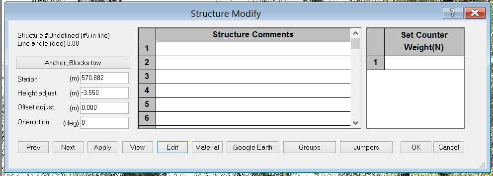
Then we need to place the structure called anchor_blocks.tow to the correct location. Structures > Add > Select Structure and place in correct location.
We can now see that we have attachment points defined for each anchor block location.
I now need to define the attachment points on the structure. In this case, I am going to modify an existing structure file and add in an extra set with three phases, for each downlead attachment point take off location.
This process will vary, depending on the type of structure file used; being either a Method 1 ‘stick structure’ or a Method 4 ‘structural model’.
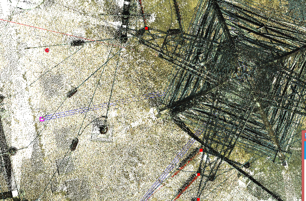
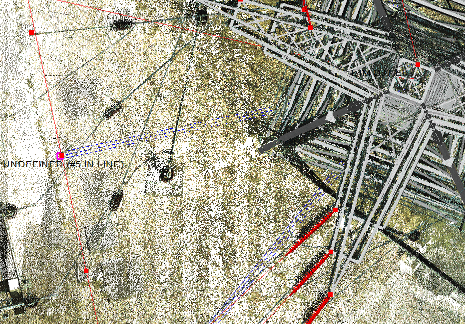
In the first instance we will look at modifying a M4 structure. After de-activating the terrain points we can clearly see the M4 structure with attachment points, the Anchor Block structure with attachment points (Structure 5). We need to place additional attachment points onto the M4 structural model.
Remembering our Geometry of the downlead attachments we can see that the downlead attachment points for Middle and Bottom phases are already defined. We only need to add in an attachment point for the top phase.
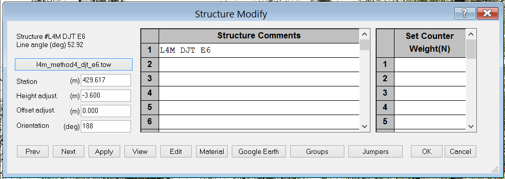
So, lets hit Structure > Modify > then Edit, which will take us into the PLS Tower environment.
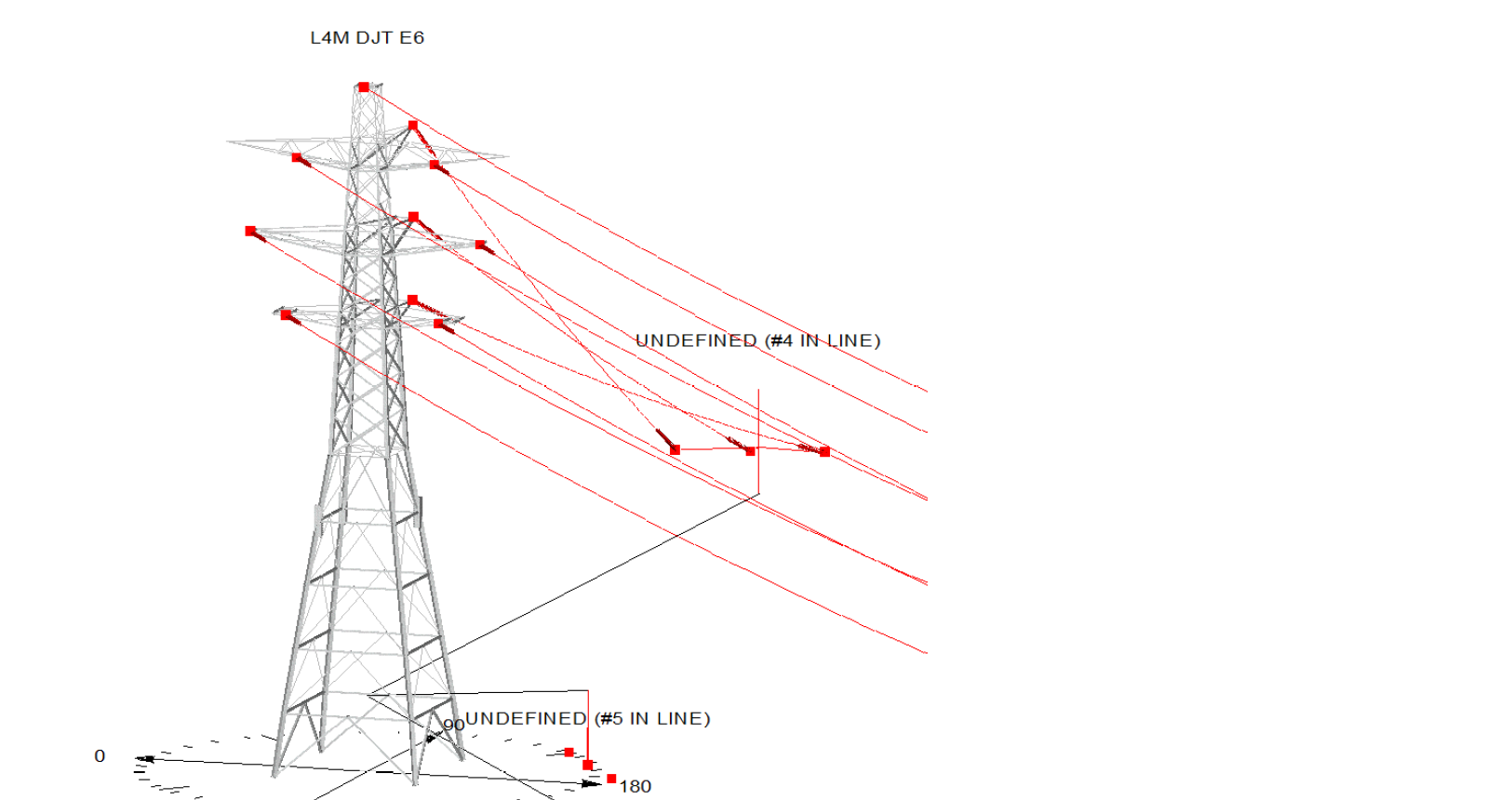
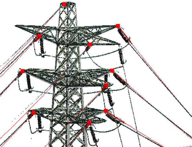
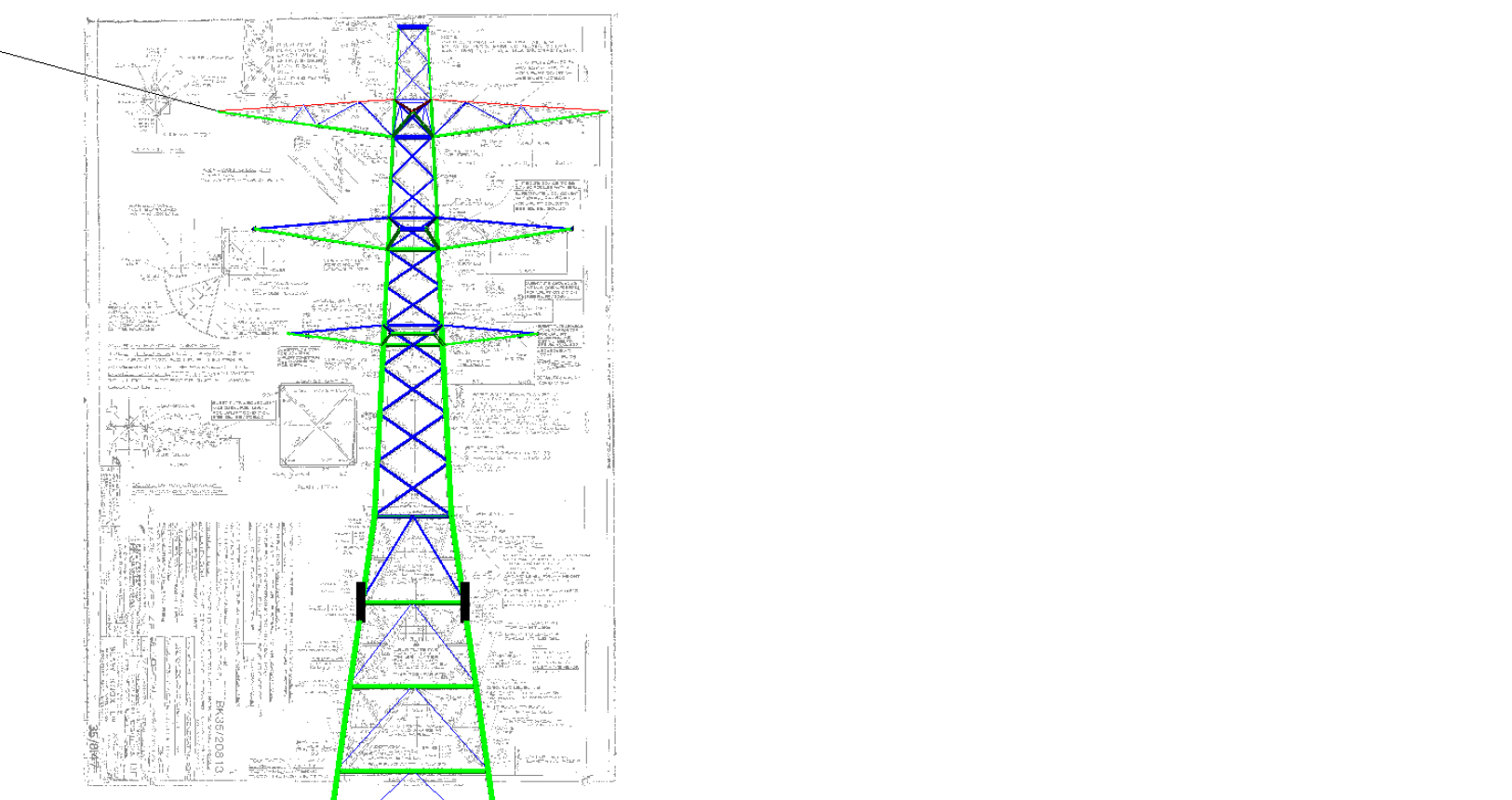
Initial View in PLS Tower shows M4 structure, validated against original General Arrangement Drawing.
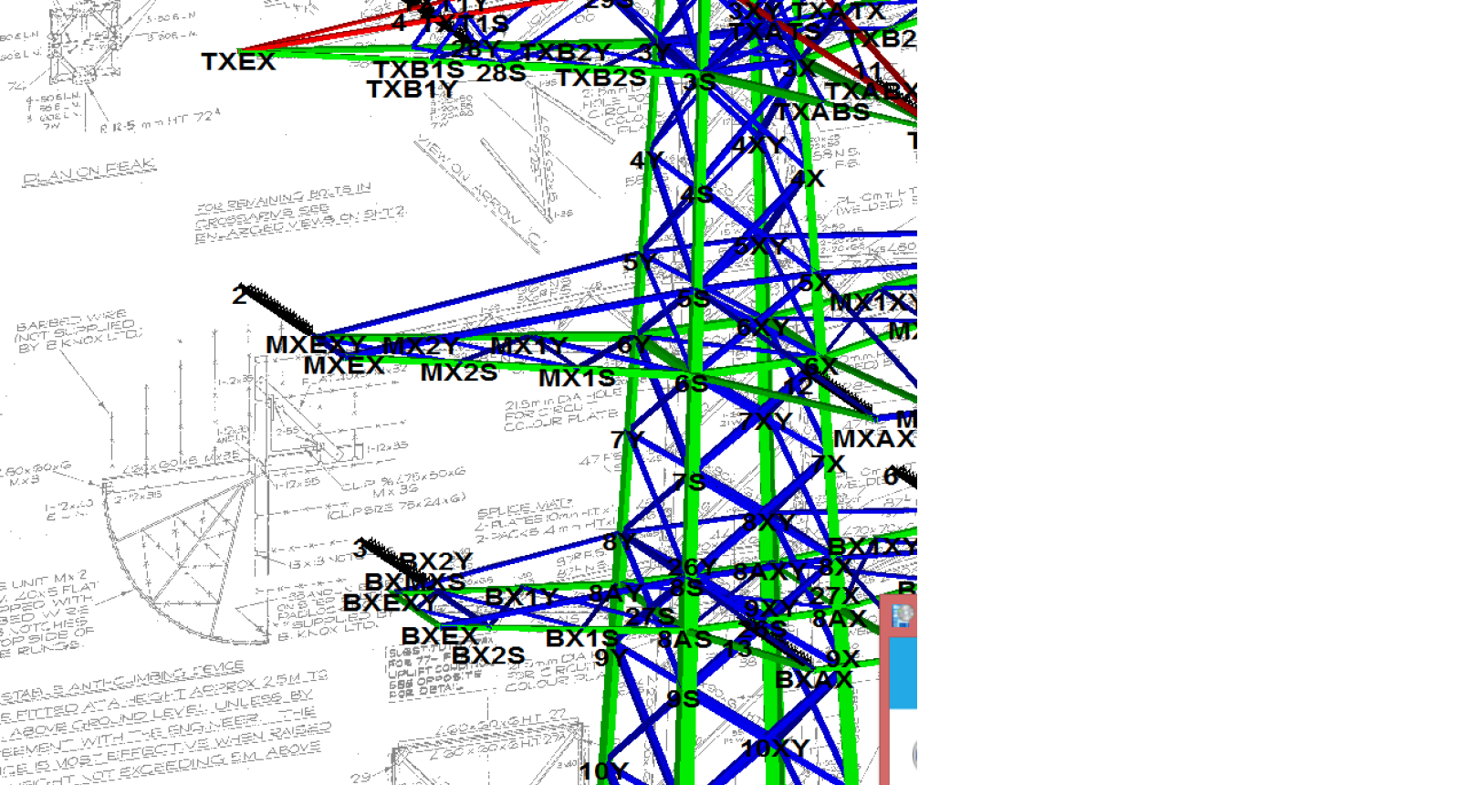
Manipulating the view I can see that the attachment points I wish to occupy are TXEX, MXEXY and BXEXY.
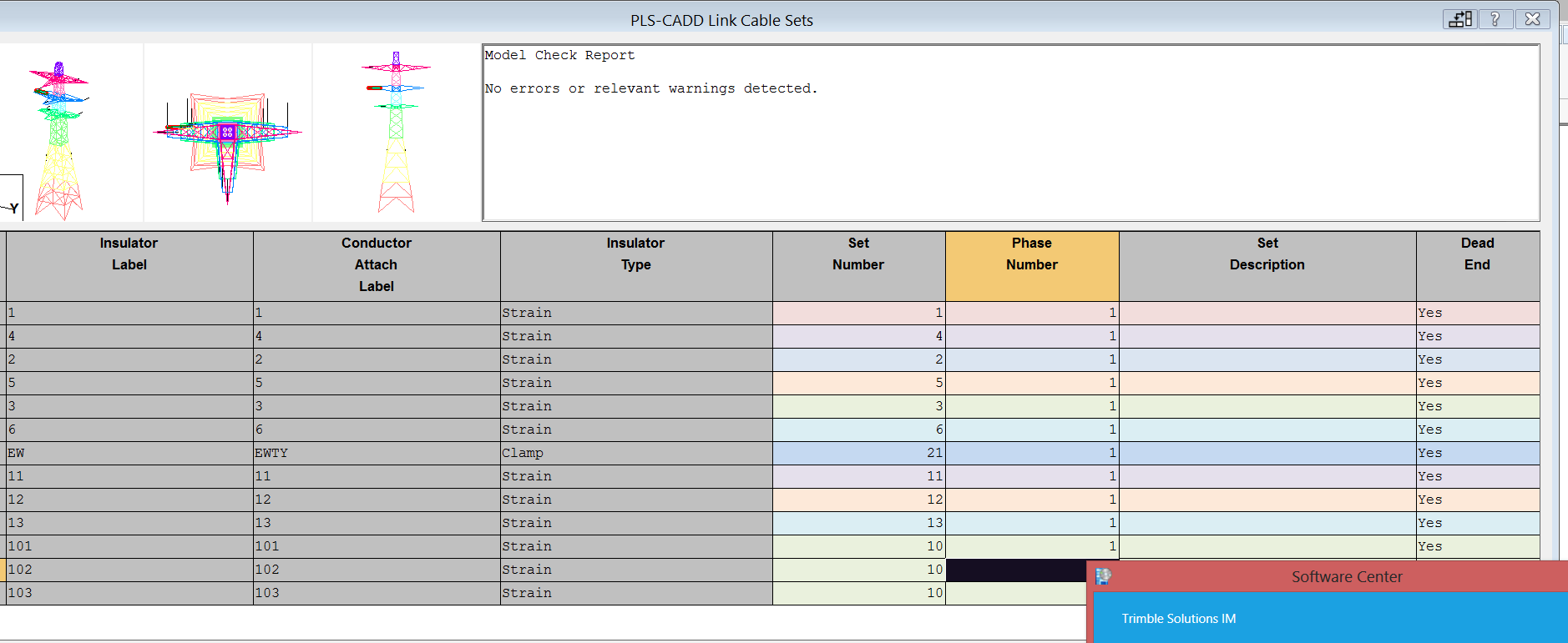
Looking at the PLS CADD Insulator Link – Geometry > PLS CADD > Insulator Link
I can see which sets and phases have been selected thus far.
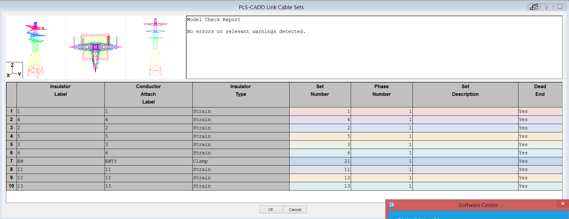
I am going to use Set 10 for my Downlead attachment points on the structure, phases 1, 2 and 3.
I add my strain insulators at the relevant points using Geometry > Insulators > Strain.

I have labelled them 101, 102 and 103; meaning set 10, phase 1, 2 and 3.
And I assign these set and phase labels in Geometry > PLS CADD > Insulator Link.
Going back into PLS Cadd we can string from Set 10 in the M4 Model to Set 1 in the Anchor Block model. We use Single Lynx at 132kV and keep all the defaults. We select a display case of 5 deg C.
We can see that our downleads to anchor blocks have been strung successfully.
The bottom take off location on the M4 structure looks incorrect.
So we can modify this by switching the location of our attachment points from BXEXY to BX2Y; we do this in Geometry > Insulators > Strain.
We can now see that the locations for all take off points are accurately defined and the geometry is good.
In the next blog I will look at Tensions and how to consider and model this within the software. Finally, we will look at creating designs for new downleads rather than modelling existing ones.
I hope this blog has proven useful and, as always, feel free to get in contact if you have any comments.
As Director of Engineering and heading up research and development at NM Group, Paul Richardson is a renowned power industry expert and long-time proponent of the use of 3D modelling in improving reliability and utilisation, while minimising cost. He is a chartered civil engineer (BEng Hons, CEng, MICE), and retains a wealth of experience, including more than 30 years of power line engineering.