Ask an Engineer – Part 2

How do you go about modelling jumpers and can you do this in PLS-CADD™?
Let me answer the latter part of the question first; yes, you are able to model jumpers in PLS-CADD™, however they are considered as catenaries with zero stiffness. It is possible to apply wind or ice loads to these jumpers and to check electrical clearances; from the jumper to the structure, and also to the insulator earth end.
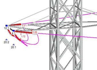
Having said that, considering how that can best be achieved goes right back to that problem of determining jumper stiffness:
- Should they be catenaries of zero stiffness?
- Or should they be rigid bars with ‘infinite stiffness’?
I have seen situations which would support both of these extremes, although generally we are looking at a stiffness somewhere between zero and infinity. So how do we determine this? Were you to pick up a 500mm long piece of Araucaria conductor, you would be pretty confident in tending toward the ‘infinity end’, while a 2m long section of Lynx conductor would have you thinking ‘no, it’s flexible’.
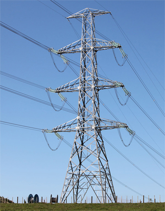
So, the apparent stiffness, for a stranded conductor, is affected by the relationship between length and diameter. What else affects the jumper shape? For higher, typically transmission voltages, the jumper typically (though not exclusively) hangs down below the insulator. For lower, typically distribution voltages, the jumper typically (though not exclusively) goes above the insulator.
Other considerations will be the way the conductor is joined to the insulator:
- Is it a bolted connection or a compression fitting?
- How long is the ‘gun end’?
- Do we consider the conductor to be fixed while within the length of the gun end and then to exhibit some flexibility when the conductor leaves the ‘gun end’?
- Do we have any jumper weights fitted, to change the shape of the catenary?
- Does the jumper go through a ‘stand-off’ insulator?
- And finally, does the connection to the insulator impart any stiffness onto the jumper shape?
So, as we can see, there are a lot of variables to be considered when determining jumper design and modelling. I have carried out modelling in both MicroStation and AutoCAD®, where I have made some assumptions about conductor behaviour, then have considered jumper swing as the angle derived from the ratio between wind pressure and conductor mass. All that I can say, is that the end result ‘doesn’t look unreasonable’. There are so many variables to be considered that the test of ‘not being unreasonable’ may be the best we can realistically expect.
As a final point, the people at PLS-CADD™ have been wrestling with some of these issues for a while, and tell us that there will be a way to include some of these considerations, when modelling jumpers in future releases of PLS-CADD™. I look forward to re-visiting this topic when the engineers in Madison have ‘done their stuff’.
As Director of Engineering and heading up research and development at NM Group, Paul Richardson is a renowned power industry expert and long-time proponent of the use of 3D modelling in improving reliability and utilisation, while minimising cost. He is a chartered civil engineer (BEng Hons, CEng, MICE), and retains a wealth of experience, including more than 20 years of power line engineering.
Paul will be answering more questions as part of the Ask an Engineer blog series. So, if you have a question about LiDAR, PLS-CADD or any aspect of power line engineering, please email info@nmgroup.com.
If you didn't catch part 1, Can you accurately model wire positions in PLS-CADD, when there is wind blowing the conductor during a LiDAR survey?, read it here.