An in depth look at modeling downleads in PLS-CADD Part 2 – How to model tension
In this latest blog I wanted to continue looking at the process of modeling ‘downleads’ in PLS CADD. As mentioned in Part 1, this topic gets a lot of interest from clients so I think it is worthy of some attention. Part of what makes it so complex is that traditional concepts such as sag have no value and tensions become very important and are incredibly sensitive to changes in span length.
In the previous blog I discussed getting the geometries right, now I will move onto modeling downlead tensions in PLS-CADD.
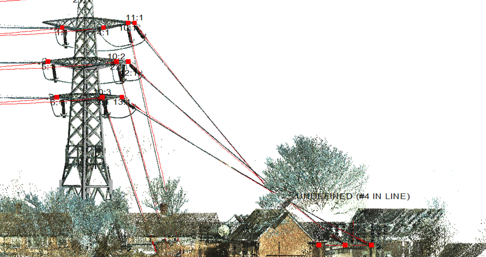
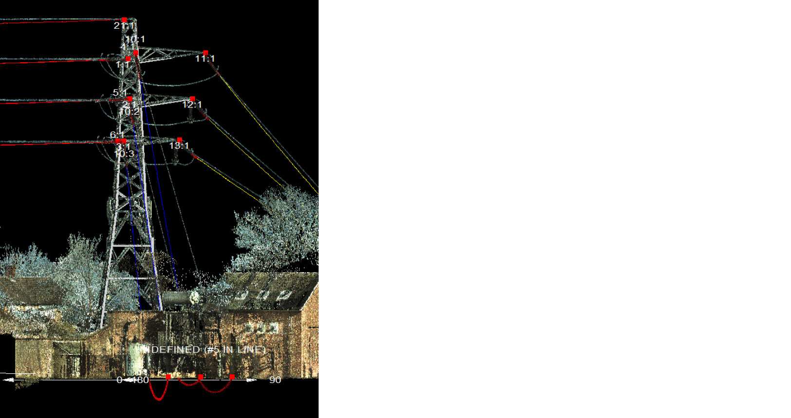
Lets go back to our worked example. In Part 1 we got the geometries looking right however, when we look at the span length we see some contradictory data. Looking at the downlead, the span length in the Profile View is showing as as 31m, yet in the Sections Table, the Equivalent Span values is showing as 2m. So what is happening here?
 The reason for this is that the equivalent span is calculated as:
Le = Square Root of [(L1^4/Z1+L2^4/Z2+Ln^4/Zn)/(L1+L2+Ln)]
Therefore, the large difference between end elevations makes the Ruling Span value meaningless.
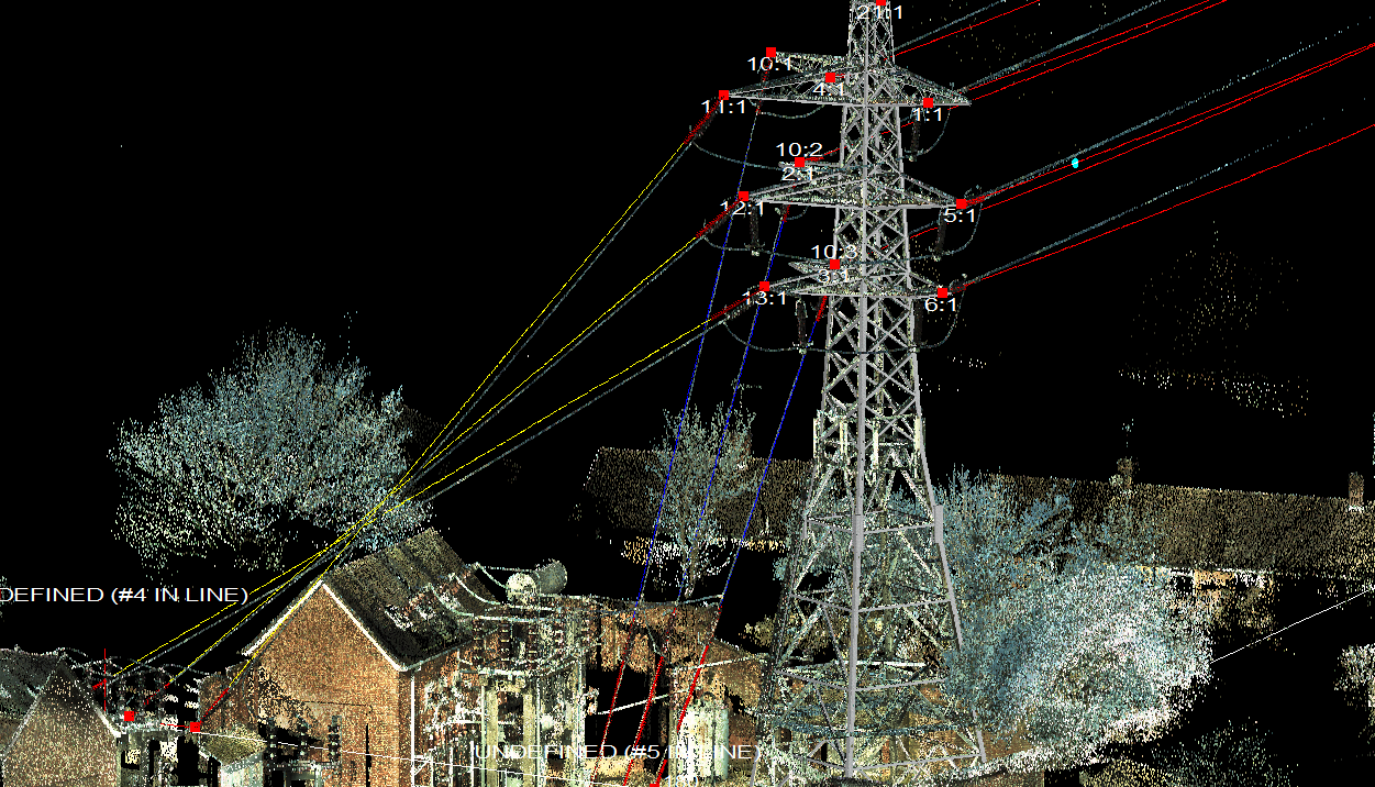
So, if we put Clip the insulators and put the Display Condition into Finite Element, all should be good, right?
Well, we can see that the Yellow ‘downleads to gantry’ are strung too slack.
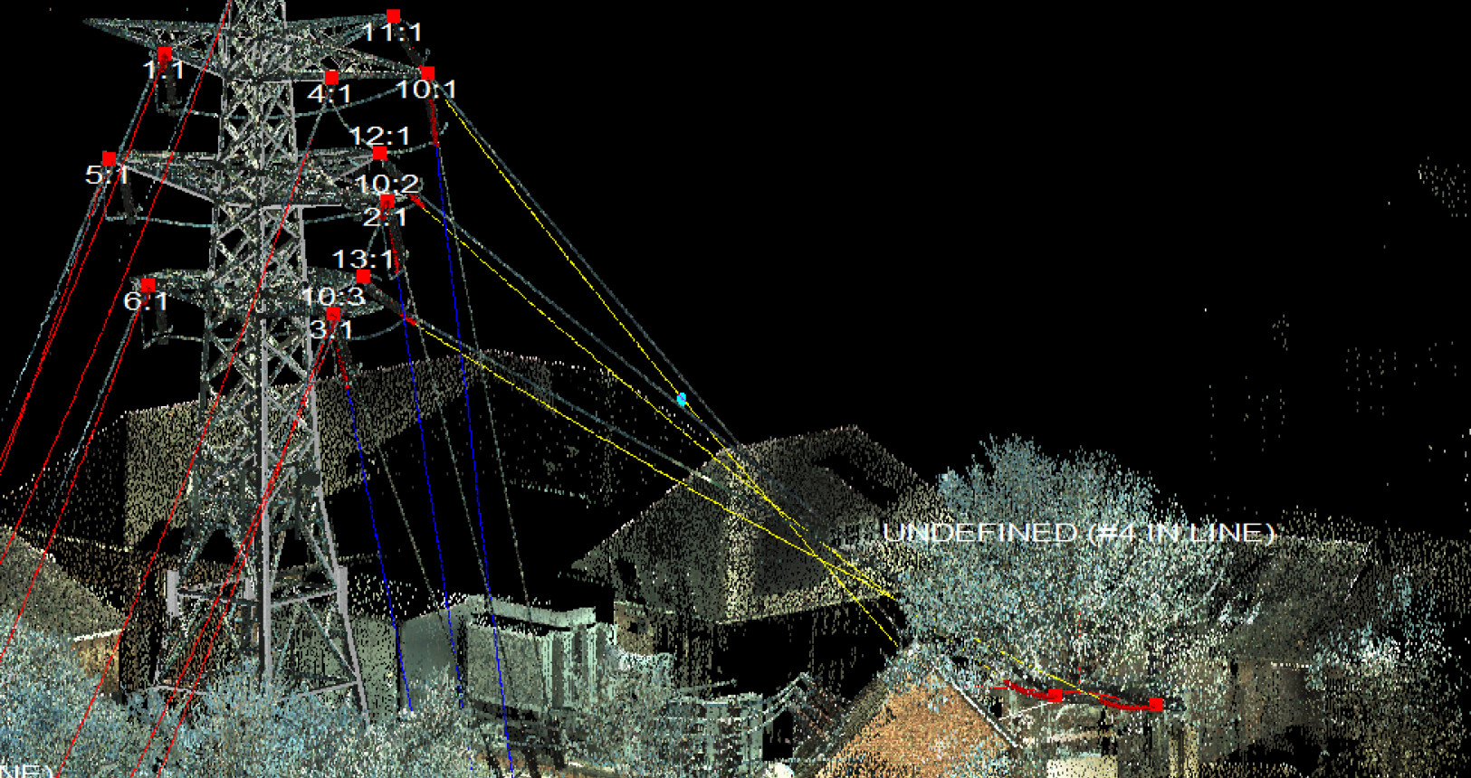
We can also see that the Blue ‘downleads to anchor blocks’ are strung way too slack.
So the question we have to ask is what are appropriate tensions?
Are we modeling existing downleads or are we stringing new? If we are modeling existing downleads we probably want to match the installed tension as much as possible, while also reflecting the distortion to sag profile caused by the weight of the insulators.
Weight of insulators in a standard span length has little impact on conductor sag, as the large span means the effect is minimal; however, for downleads with short spans, the effect is significant.
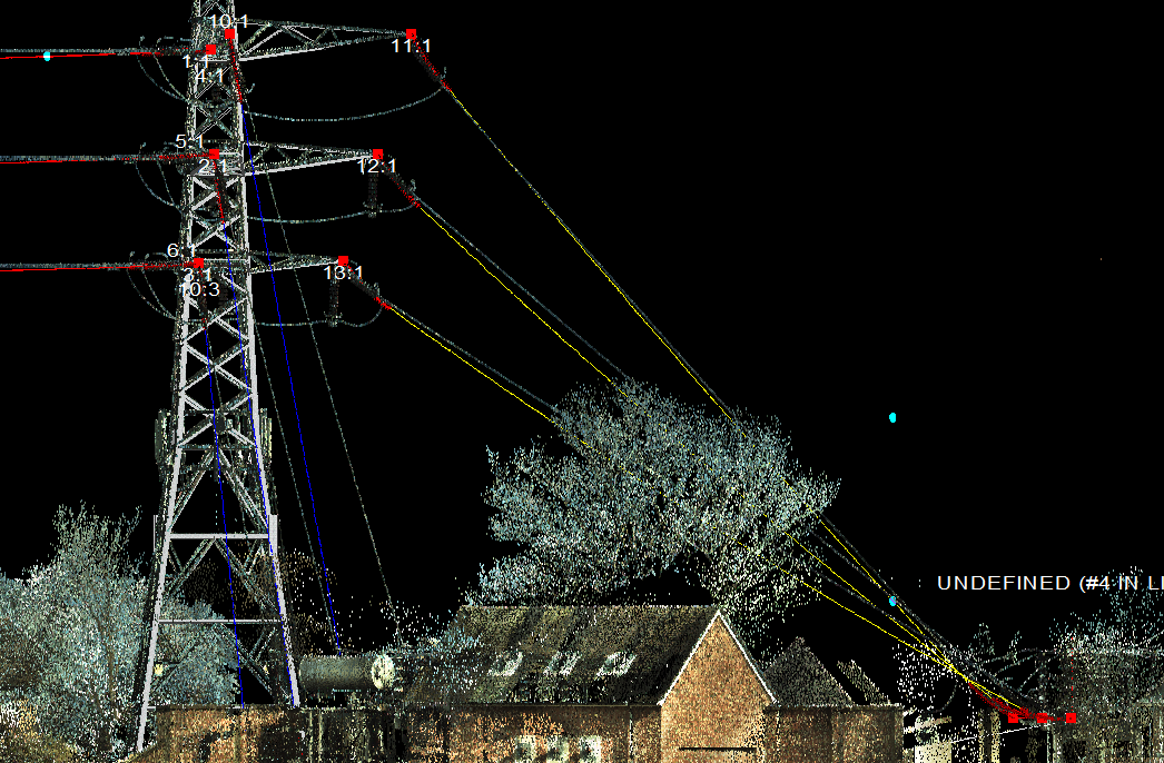
So, let us try to model up the Yellow downleads to Gantry.
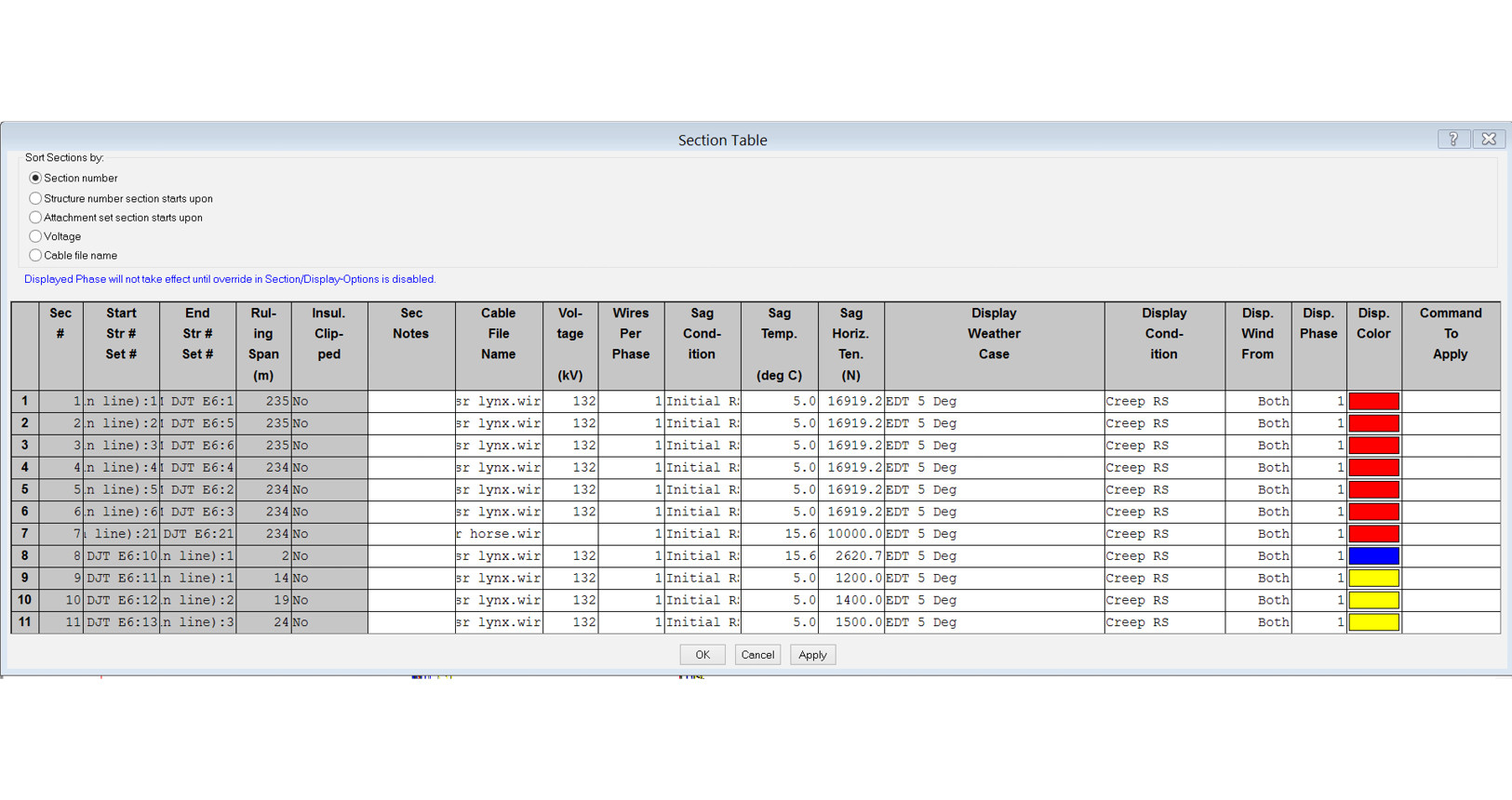
In ruling span conditions the downleads were strung to 1200, 1400 and 1500N respectively, they produced a reasonable match to the LiDAR shots, however did not account for the additional weight of the insulators.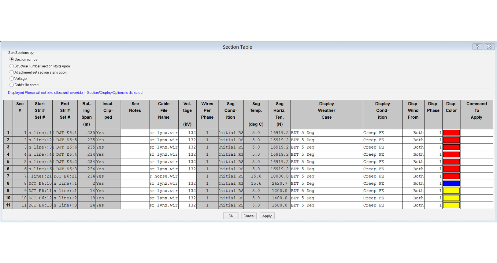
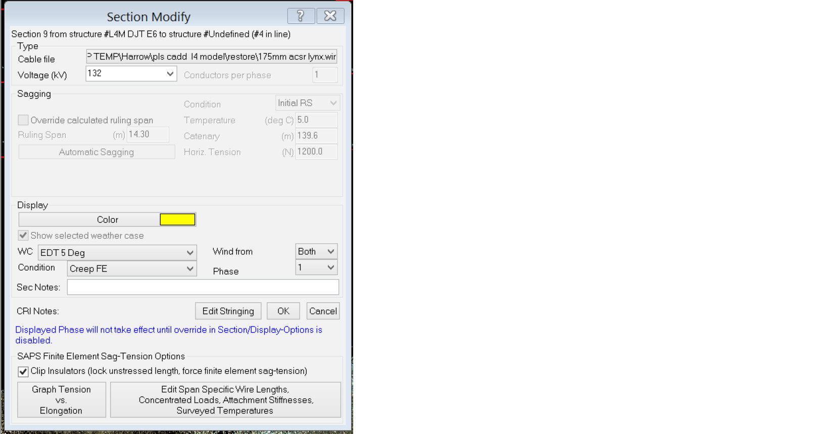
To get the correct profile we need to vary the tension for each downlead. In Finite Element environment this is accomplished by varying the unstressed length of each conductor.
We access this option by using Sections > Modify > Edit Span Specific Wire Lengths.
The ensuing dialog box looks like this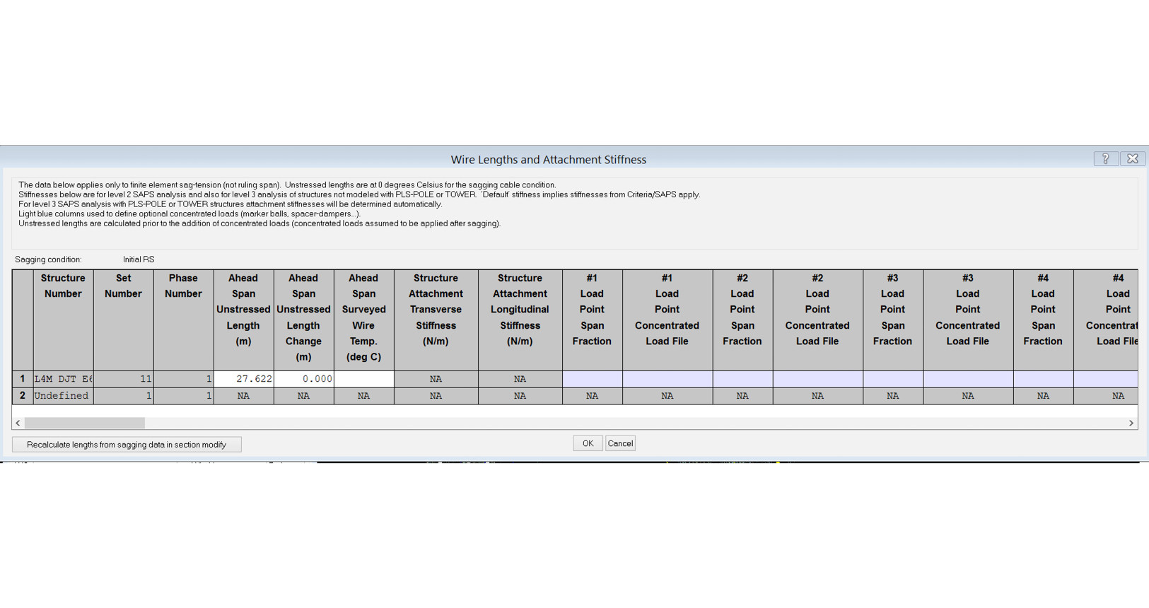 To increase the tension, I must put in a negative length change into the ‘Ahead Span Unstressed Length Change’ box.
I tried Minus 1m (-1m) but as can be seen, that makes the downlead now too tight.
Trying a value of -0.1m matches the sags well, but doesn’t match the ‘belly’ of the insulators, which suggests the weight value for our insulators is too large.
Going back in to PLS CADD and modifying the Insulator Weights and Unstressed Lengths finally gets the desired result.
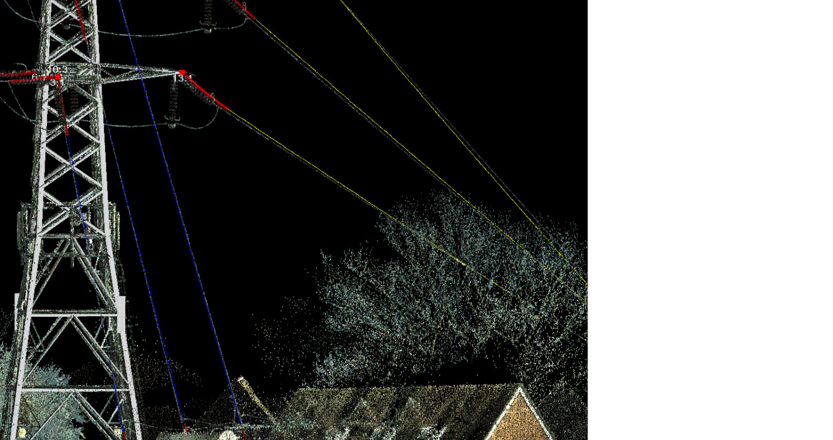
The downleads to anchor blocks are even more sensitive to the changes to unstressed length, with reduction of slack of 2cm for the top phase and 1cm for the bottom phase; those adjustments ensured a perfect reflection of existing downlead sag / tension behavior.
What can be clearly seen is that insulator weights and conductor tensions have a huge impact upon conductor profile, while sag is practically meaningless.
In the final blog in this in-depth guide I will be looking at creating designs for new downleads rather than modeling existing ones.
I hope this blog has proven informative and, as always, feel free to get in contact if you have any comments.
As Director of Engineering and heading up research and development at NM Group, Paul Richardson is a renowned power industry expert and long-time proponent of the use of 3D modeling in improving reliability and utilization, while minimizing cost. He is a chartered civil engineer (BEng Hons, CEng, MICE), and retains a wealth of experience, including more than 20 years of power line engineering.