Modeling downleads in PLS-CADD - Part 3 - Modeling new designs
In my final blog, I wanted to finish looking at the process of modeling ‘downleads’ in PLS CADD. This topic gets a lot of interest from clients so I think it is worthy of some attention. Part of what makes it so complex is that traditional concepts such as sag have no value and tensions become very important and are incredibly sensitive to changes in span length.
In the previous blog, I discussed modeling the geometry and tensions of existing downleads. However, what do you do when you are designing a downlead from scratch? In this article, I will look at creating a new as-designed downlead in PLS-CADD.
What is a Downlead? View Part 1 of our blog series to cover the important concepts.
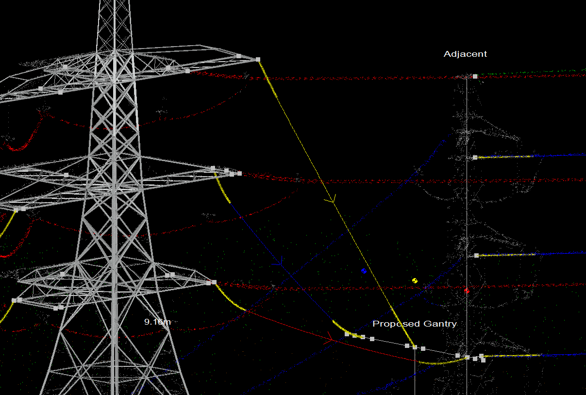
When modeling a new design the first requirement is to define the geometry of the downlead attachment points. This will probably require the use of a General Arrangement Drawing of the Terminal Structure and the Substation Gantry to understand the locations of the available attachment points.
The ‘proposed substation’ gantry is modeled as a M1 ‘stick structure’ its geometry being defined using the ‘structure data editor’ as shown.
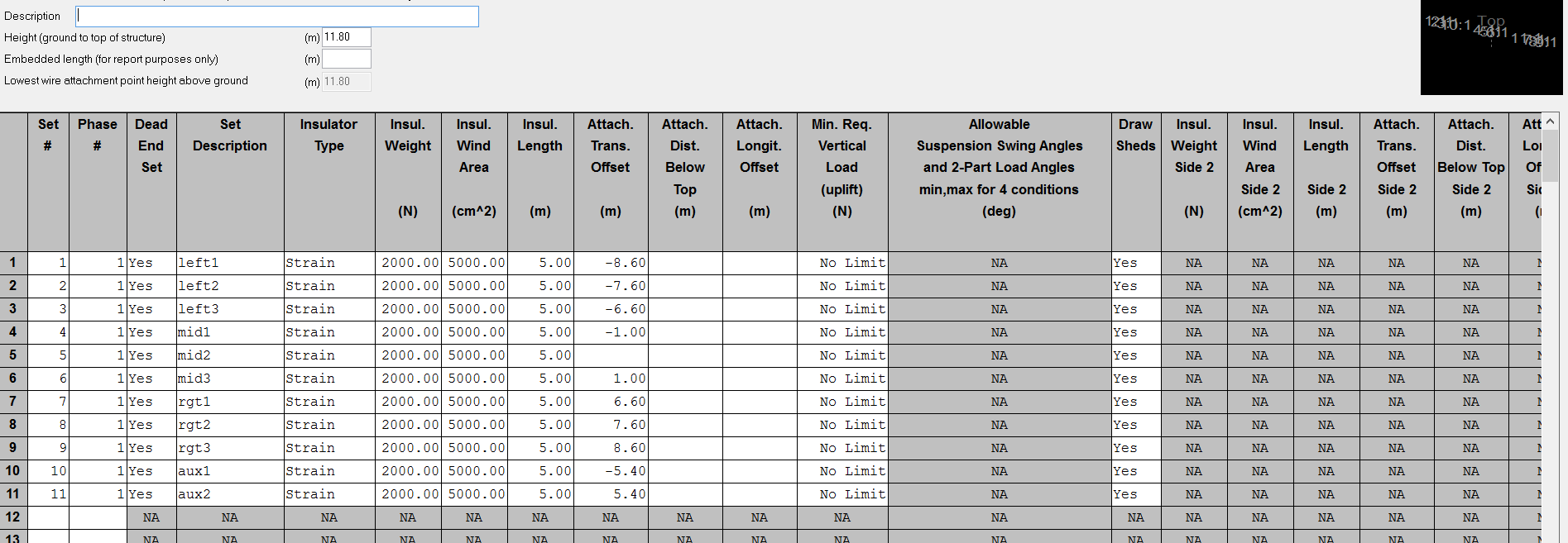
Each phase (Left, Middle and Right) has three alternative take off locations, which can be adjusted to achieve the required phase-to-phase clearances under a number of loading conditions.
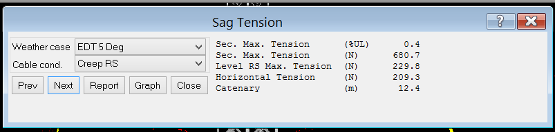
Now that we have defined the downlead Geometry, the second thing we need to define is the downlead sag – tension. As discussed in the topic of modeling existing downlead tensions, the tension of the downlead is a far more useful measure than sag.
Defining downlead Tension
There are some different approaches that can be taken to define the downlead tension. I shall refer to two possible methods; these are the ‘Ultimate Tension’ and the ‘Nominal Tension’ approaches.
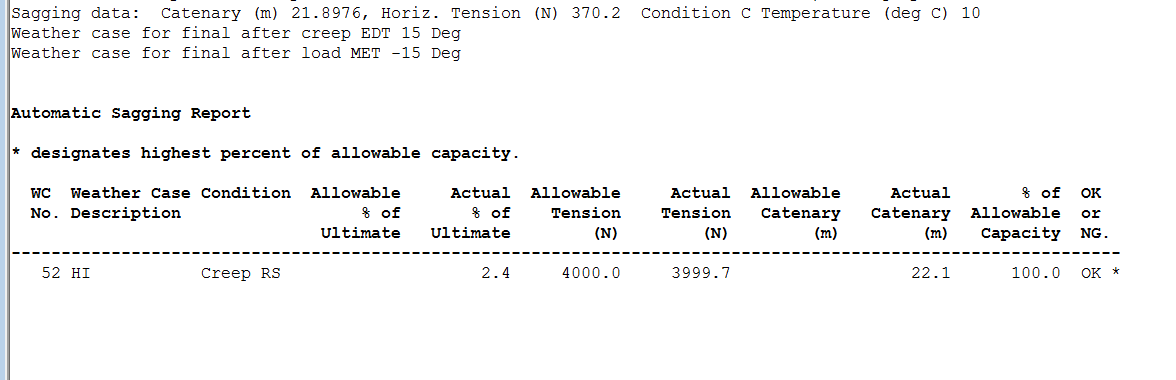
Ultimate Tension – in this case, we set a limit to the downlead tension at a loaded weather case (high wind, heavy ice or a wind / ice combination) so let us say that the allowable tension per phase at the gantry is 4000N. We can set this as a ‘sagging basis’ for the heavy ice condition thus:
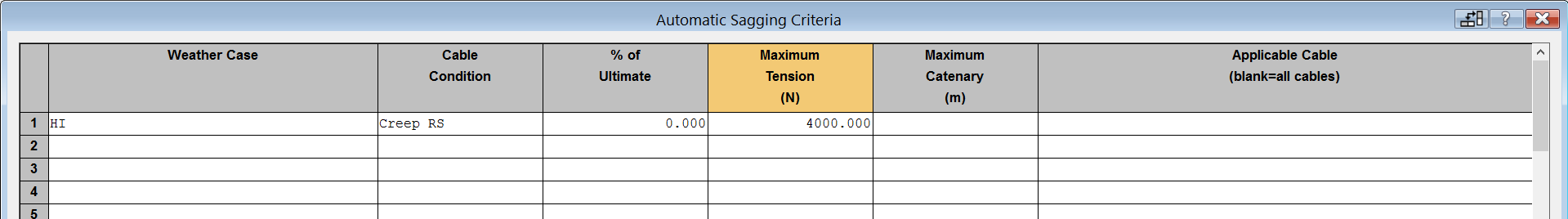
Now when we run the automatic sagging routine it will sag the downlead at the maximum tension possible that will not exceed 4000N under the heavy ice case. Sections > Modify > Automatic Sagging
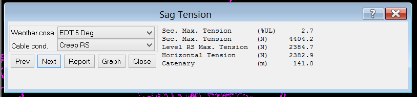
We can use the Sections > Sag-Tension command to find the tension under any other weather case (e.g. everyday 10 deg C).
Nominal Tension – In the ‘nominal tension’ case, we adopt the old ‘rule of thumb’ whereby downleads would be sagged to a tension of 7000 lbs per sub-conductor at the Maximum Working Tension (MWT) basis. So here we would set up a ‘weather case’ Criteria > Weather
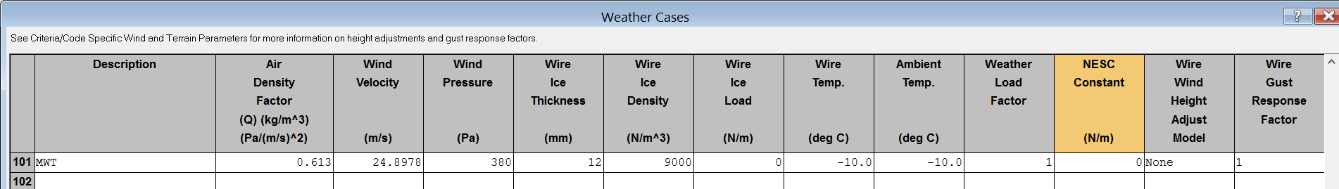
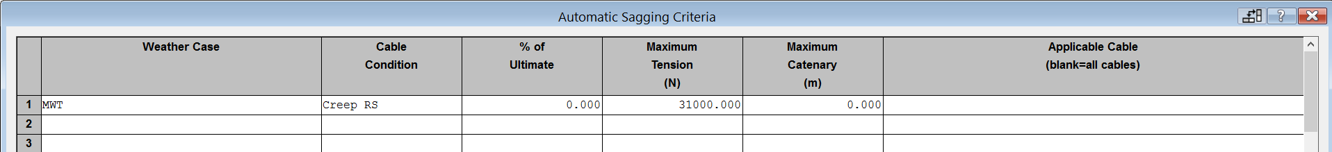
For the MWT basis (380 N/sqm and 12mm Ice at 900kg/cum density) we then need to set up a sagging basis in Sections > Automatic Sagging.
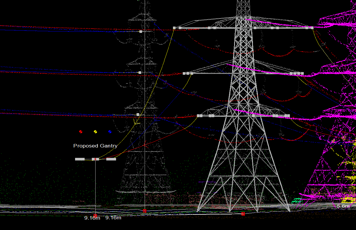
We have used that automatic sagging basis for the yellow phase here; as you can see it looks quite tight.
A further technique, often used for onsite stringing and sagging is to ensure ‘by eye’ that there is sufficient ‘belly’ in the insulators.
We can use the graphical sagging technique to approximate that approach.
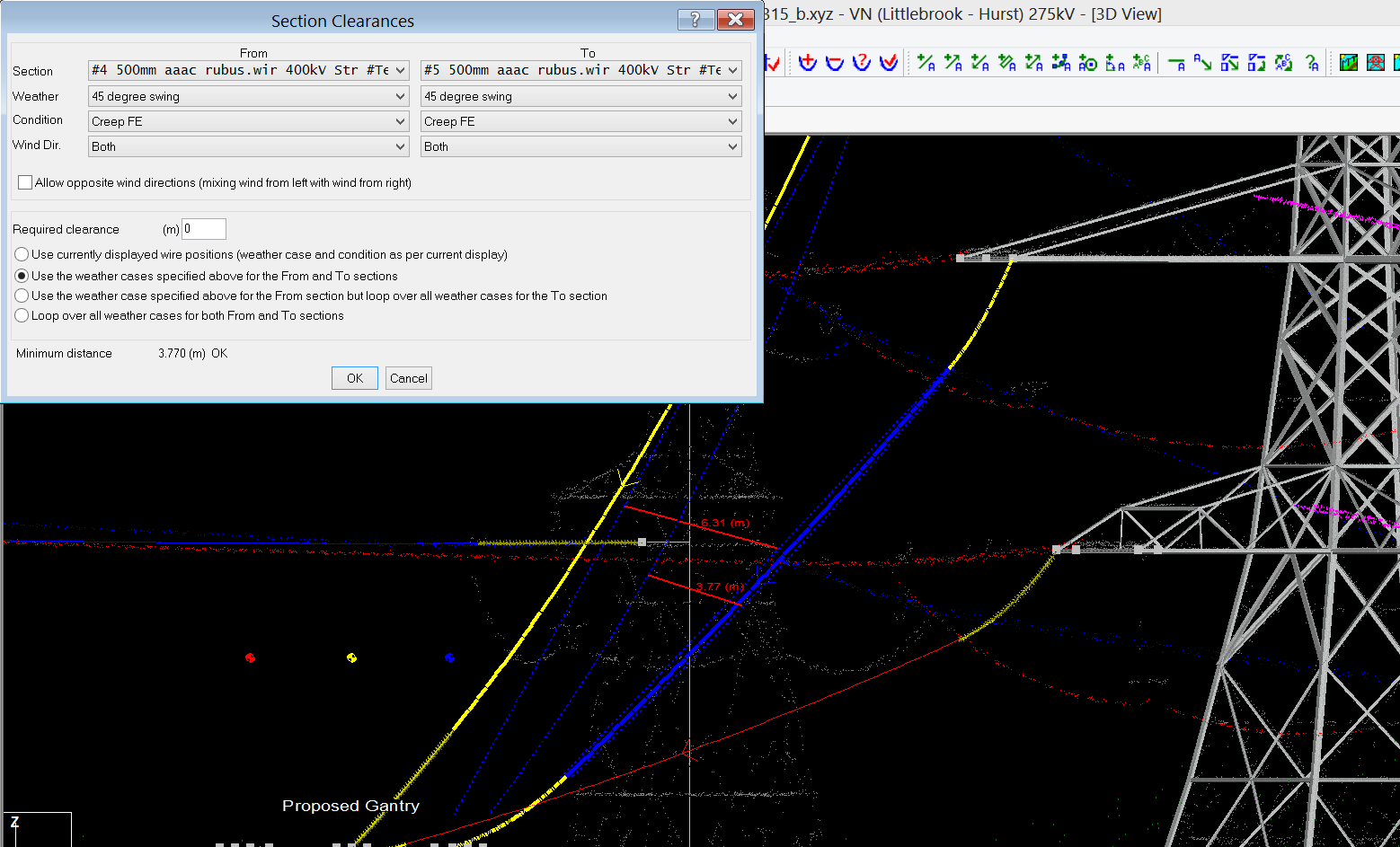
Now that we have defined our tension, using one of the methods described above, we can check clearances by using Sections > Clearances > Between Sections
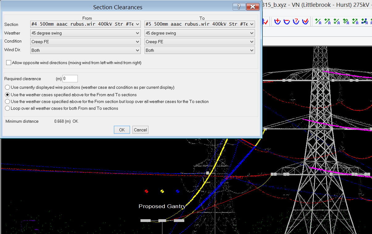
Where we need to select between which phases we are checking clearances and under which conditions, in this case we are checking Sec 4 v Sec 5 and are checking both at the 45 degree swung condition.
We can see that the clearance is quite low; this may be because of the low tension on the yellow Top phase.
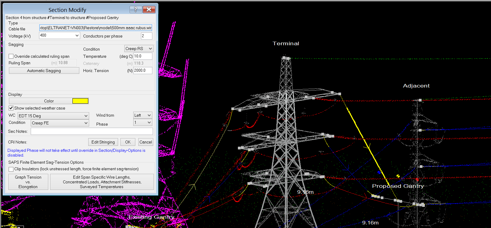
So we may wish to increase that tension, I’m going to increase it to an arbitrary 500 N, by using Section > Modify

At that new tension, we can check clearances again. Note this is ‘Horizontal Tension’.
There may be some iteration required to get the correct ‘trade off’ between allowable tensions and clearances, or possibly a requirement to choose alternate attachment point locations for the downlead connection.
Well folks, that concludes my blog series on modeling downleads in PLS-CADD. I really hope this blog has proven interesting and informative. If you have any questions or have any other topics that you would like me to cover, please get in touch at info@nmgroup.com
As Director of Engineering and heading up research and development at NM Group, Paul Richardson is a renowned power industry expert and long-time proponent of the use of 3D modeling in improving reliability and utilization, while minimizing cost. He is a chartered civil engineer (BEng Hons, CEng, MICE), and retains a wealth of experience, including more than 20 years of power line engineering.