The evolution of re-conductoring studies
By Paul Richardson – Director of Engineering
This blog series looks at the evolution of geospatial technologies, and how they have played a key part in improving the safety, reliability and utilization of power networks. Previously in this series we have discussed advances in thermal ratings studies, new line design and optimization and asset inspections.
In this blog I will be considering re-conductoring. Specifically how advances in LiDAR and CAD technology, have transformed the way that re-conductoring studies are considered and actioned.
What is re-conductoring?
Re-conductoring is the replacement of an existing conductor with another. This may be due to increased rating needs, or simply due to the failing condition of an existing conductor. If the replacement is ‘like for like’, it may be referred to as ‘refurbishment’. The other parts of the conductor system; the insulators, supports, shield wires and foundations may or may not be replaced or reinforced at the same time.
Why is this important?
In the past load flows were typically unidirectional, with known sources of supply and known centers of demand. These patterns of generation and demand have since changed, and in many cases there is an increased requirement for power flow.
Many assets are now operating well beyond their expected lifespan. The ‘refurbishment tsunami’ which has been expected in many developed countries since the 1980’s has been continually deferred as asset life has been extended. This has led to piecemeal replacement of failing assets. For example, consider an original ACSR conductor that has been found to have core deterioration requiring replacement but where the remaining elements of the conductor system (the insulation, the structures and supports) are suitable for continued operation.
Increased demand in rapidly developing countries have meant that generous provisions for future growth of power flows have been completely outstripped and power corridors require massive uprating.
Finally, in many localities there is loud political opposition to the siting of new power lines. Here, the utility is faced with a need to provide additional capacity on essentially the same assets.
Even generous provisions for future power supply have been outstripped by demand
The original way of doing this
Conductors would have typically been replaced with a ‘like for like’ or a modern equivalent. Loading scenarios would then have been selected on a ‘deterministic’ basis. A particular structure type would have been designed to withstand the loads applied by a deterministic loading event for a given set of allowable wind and weight span limitations.
If an increase in conductor weight was required, the allowable weight spans would be modified to suit and checked for compliance. Similarly, where an increase in conductor diameter and hence wind load was identified, the allowable wind span would have been modified and compliance checked once more.
Should these limits be exceed then then the structures, insulators and foundations would then have to be considered for either replacement or reinforcement.
The evolution of re-conductoring
There are now four key areas which allow us to perform re-conductoring more effectively.
- The transition from deterministic to probabilistic design codes, taking into account the actual geographic location and altitude, terrain type and adjacent spans with any associated angles of deviation.
- The larger selection of conductor types and sizes, including HTLS (High Temperature Low Sag) conductors.
- The availability of engineering tools, such as PLS-CADD™, which provide precise calculations of applied loadings and available structure capacities, using these probabilistic design codes.
- The availability of LiDAR datasets, to populate these engineering tools and allow exact calculation of structure loadings and capacities.
The availability of these four items means that the electrical load transfer capacities, of multiple conductors and their specific site specific loadings can be accurately determined.
This means any structural reinforcements required can be identified and scheduled. Secondly, computer modeling can objectively rank the different options, each with the specific electrical capacities, structural loading reinforcement schedules and costs.
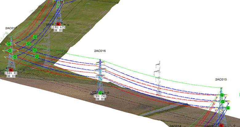
Structures assessed in PLS-CADD™ to consider their site-specific loadings
Key observations
One of the key improvements of this approach is that specific reinforcements can be clearly defined. For example, where previously analysis may have shown that all structures within >80% of allowable wind span required reinforcement, it is possible to identify only the specific structures that require reinforcement. More than that, the use of structural analysis tools such as PLS Pole and Tower can drill down to identify only the failing members within those identified structures; even detailing the precise mode of failure for each member identified.
Taken to an extreme, this may mean that an earlier analysis which showed 90% of tangent structures required reinforcement following re-conductoring now shows that only one structure requires reinforcement. For this structure there is only one failing member, and that member is failing in tension. That failure can be resolved by only replacing the existing mild steel bolts with high yield bolts of the same diameter. The analysis accurately identifying the remediation required and significantly reducing the potential capital cost.
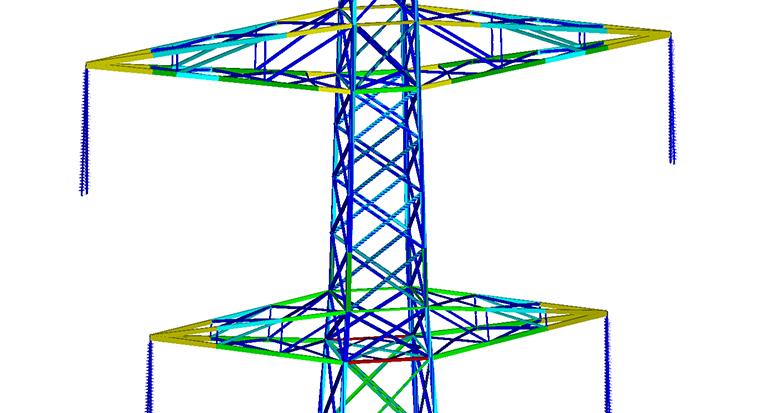
A detailed look at a failing structure shows that only one member is overstressed
In conclusion
The switch of design methodology, the availability of engineering analysis tools, the LiDAR data to populate these tools and the profusion of available conductor materials and types, mean that there are more viable options available. Multiple conductor systems can be considered and a precise scope of work and reinforcement requirements identified.
Engineers can now receive a detailed schedule of electrical load transfer capacities, demonstrate how this affects transmission losses, the effect on kgCO2, what works are required and the duration of those works. It is also possible to provide accurate costings of each option. Armed with this information, a network operator can be confident that the most appropriate re-conductoring option is selected.
The evolution of geospatial data combined with advanced tools and software has meant more precision is available when completing a re-conductoring study. This in turn means that in many cases, increased line capacity is available without the expense of major capital works.