Top five engineering questions

LiDAR data provides high resolution, accurate data perfect for a number of engineering applications. The technology is specialist though and it is only natural that many engineers want to understand more about how LiDAR, geospatial analysis and PLS-CADD modeling can help meet their specific challenges. Read on for the five most frequently asked questions to do with engineering.
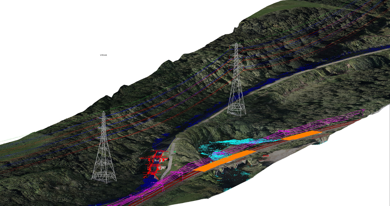
1) How do you model conductor sag and sway using LiDAR?
Originally most relevant to transmission utilities, due to increasing cost efficiencies more distribution utilities are also modeling sag on higher voltage circuits.
The technique uses LiDAR and geospatial analysis to scan the 3D position of a conductor at a point in time. Then using an industry standard calculation (IEEE/CIGRE) we can combine this with line load and ambient temperature data. Along with the conductor type, we can model the sag and sway for any specific loading condition. Usually modeling the sag at maximum operating temperature to verify wire clearances are within statutory requirements.
2) How accurate are PLS-CADD models?
PLS-CADD models typically use some kind of spatial data input. Usually the position of structures and wires on existing infrastructure and the topology of terrain for the area. The simple answer here is in absolute terms the model is as accurate as the spatial data. If you use relatively coarse satellite data to position towers then of course it will not have the absolute accuracy of a terrestrial LiDAR scan.
The more important point is choosing the input data that best meets the needs of the project. This will be quite different if you are doing a feasibility scan of several route options vs a structural modification of a tower component. The higher the accuracy level required the more costs go up so it is a trade-off. With aerial LiDAR it is possible to get 50 mm accuracy, but for most of the engineering applications we work on a typical range is 150mm – 200mm.
3) Do we need to model the powerlines every year for engineering purposes?
The answer to this question depends on the intention of the dataset. If you want to monitor change then frequent surveys are one method of doing this. If you are determining your thermal ratings this may be determined by your regulatory environment. Indeed many clients will also phase the collection of data to best meet budgets requirements. Wires and towers remain static; normally it is the surrounding environment that is changing. This might be vegetation growth, unauthorized building work in the ROW or earth movement like subsidence. Therefore, the question becomes how much of this change do you need to see in order to run your network as effectively as possible. The key is working closely with a supplier to build an engineering survey schedule that best meets your networks unique needs. There is never a one-size fits all approach.
4) Can you automatically optimize tower spotting using software or does it always need engineering judgment?
Data inputs such as LiDAR allow for incredibly rich definition of the line route. Inputting this into PLS-CADD software allows structural, geometry and cost databases to be set up. This software then allows every potential structure to be tried in every possible location. Automatically determining the least cost solution that meets clearance and structural requirements.
However, the judgment comes in when deciding what restrictions to place on the software. Here you need human intuition and experience to ensure you designing to code compliance. For example, setting up additional cost zones and defining the structure cost database.. Therefore, it is very true to say the software will optimize, but you need engineering judgment and expertise to use the tool.
5) How can you provide remediation designs for constraining circuits?
An experienced engineering team can identify constraints and specific mitigating spans using PLS-CADD. This software also enables the design of a variety of remediation options. One you have an accurate 3D CAD model of a circuit you can then test different scenarios. This achieved using precise calculations for applied loadings and available structure capacities, against the relevant design codes. Options include re-conductoring, suspension clamp offsets, modifications or additional structures as well as a number of other analyzes. A good company should be able to provide costings for each option as well as a recommendation.