Ask an Engineer - Part 4
How do I go about classifying and modeling distribution wires?
Classifying a distribution network, especially in the urban environment can be very challenging. Different wires coming from seemingly endless directions make modeling this a complex issue. However, by looking for the signs it is possible to begin to make sense of, untangling if you will, the wirescape.
Let’s start by defining what the ‘urban jungle’ or the ‘wirescape’ actually is. This is often influenced by geography and the custom and practice of a particular country, state or region. For example in the UK it would be unusual to see poles or structures with both transmission and distribution voltage levels. In the USA this is commonplace. This is often because the UK would have different utilities which own and operate the distribution and transmission networks, while in the USA they often belong to the same company.
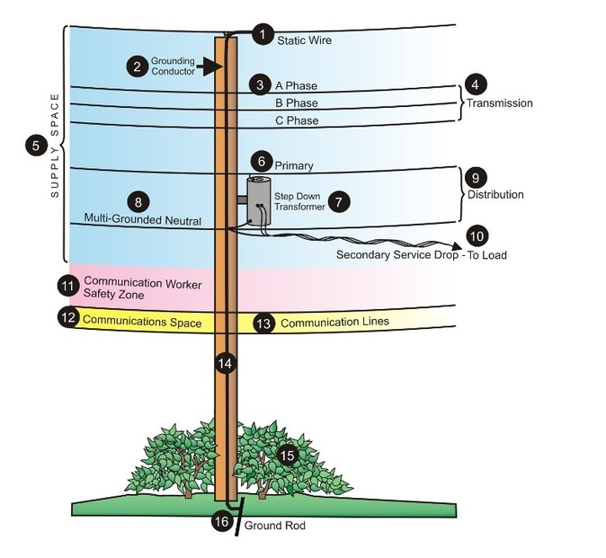
Image taken from http://www.psc.state.fl.us/ConsumerAssistance/UtilityPole
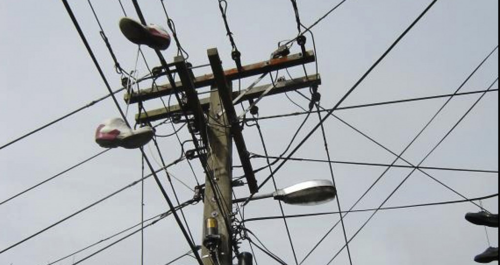
Typically, on a power line, we may have one or more shield / ground / earth wires. Commonly located at the top of the pole to provide protection from lightning strike. Below that we may have transmission voltages; for the sake of this article these are classified as 33 – 132kV and above. This is country dependant and I realize that some utilities would consider the 33-69kV range as ‘sub transmission’.
Below the transmission wires we may have one or more of what is called ‘distribution platforms’. Here we will find phases of wires at distribution voltages (typically up to around 22kV).
Depending on the three phase arrangement of the distribution system, it could have four wires (Wye, Y or Star) where there are three phases of power cables and one neutral wire, providing a return path, grounded at each pole (or sometimes every so many poles). It may also have three wires, in which case it will be a delta configuration system.
Below the distribution primary we may have secondary distribution, at yet lower voltage, which may be powering street lights or traffic signals, or could be a service drop to a building.
There would now be a gap of at least 40” or 1m, which is the ‘Communication Worker Safety Zone’ before we may encounter one or more additional wires of telecoms, cable TV etc. It should be noted that the shoes thrown over the top of the wires, though omnipresent, do not contribute to the operation of the power line.
How is it possible to determine which type of wire classification is appropriate?
So the broad scheme of classification is therefore:
- Shield / Ground / Earth wire
- Transmission voltage wires
- Primary Distribution voltage wires
- Neutrals and Secondary / service wires
- Telecommunications, CATV etc.
One of the more difficult areas for detailed classification is to separate the wires in the Distribution Power Space into Primary Distribution, Neutral, Secondary and Service Wires. So lets run through some examples.

In the image above we can see that the highest voltage is circa 10kV (single insulator shed), it is actually 13.8kV. So we don’t have any shield wire or transmission phases.
We can see some wires a couple of feet below the primary distribution level and a larger gap to further wires beneath.
Looking at the Primary Distribution level, there are three wires; this means it is unlikely that the neutral is co-located at the Primary Distribution level. The wires below seem to be duplex and seem to be connected to both the Pole mounted transformer and the Street Lighting. It is probable therefore that these are service wires. Clues are:
Presence of a Pole Mounted Transformer (PMT), presence of Street Lighting, Wires seem to be in Duplex or similar arrangement.
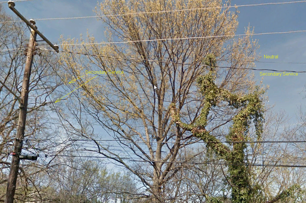
Again in the image above the largest voltage is circa 10kV, so that is the Primary Distribution Voltage. There are no shield wires or Transmission Wires to consider. We have a small gap to a pair of wires, then a larger gap to two more wires. The lowest wires, below the large gap (circa 4 feet) will be Telecommunications / CCTV. The wires below the smaller gap, circa 1-2 feet will be Secondary / Service or Neutral.
The presence of Street Lighting and also Duplex Service drops off to adjacent housing indicates the presence of Secondary / Service Wire. Looking at the two wires they are markedly different, one being of Duplex Construction, the other bare metal. It is highly likely that the bare metal will be Neutral while the Duplex will be Secondary Distribution / Service.

Three phases of Primary Distribution, above a PMT with two wires below. Then large gap to further wires below. The wires below the large gap (circa 4 feet) are telecoms, the wires below the PMT are neutral and secondary / Service. It is highly likely that the bare wire is the neutral and the duplex is the secondary / service.
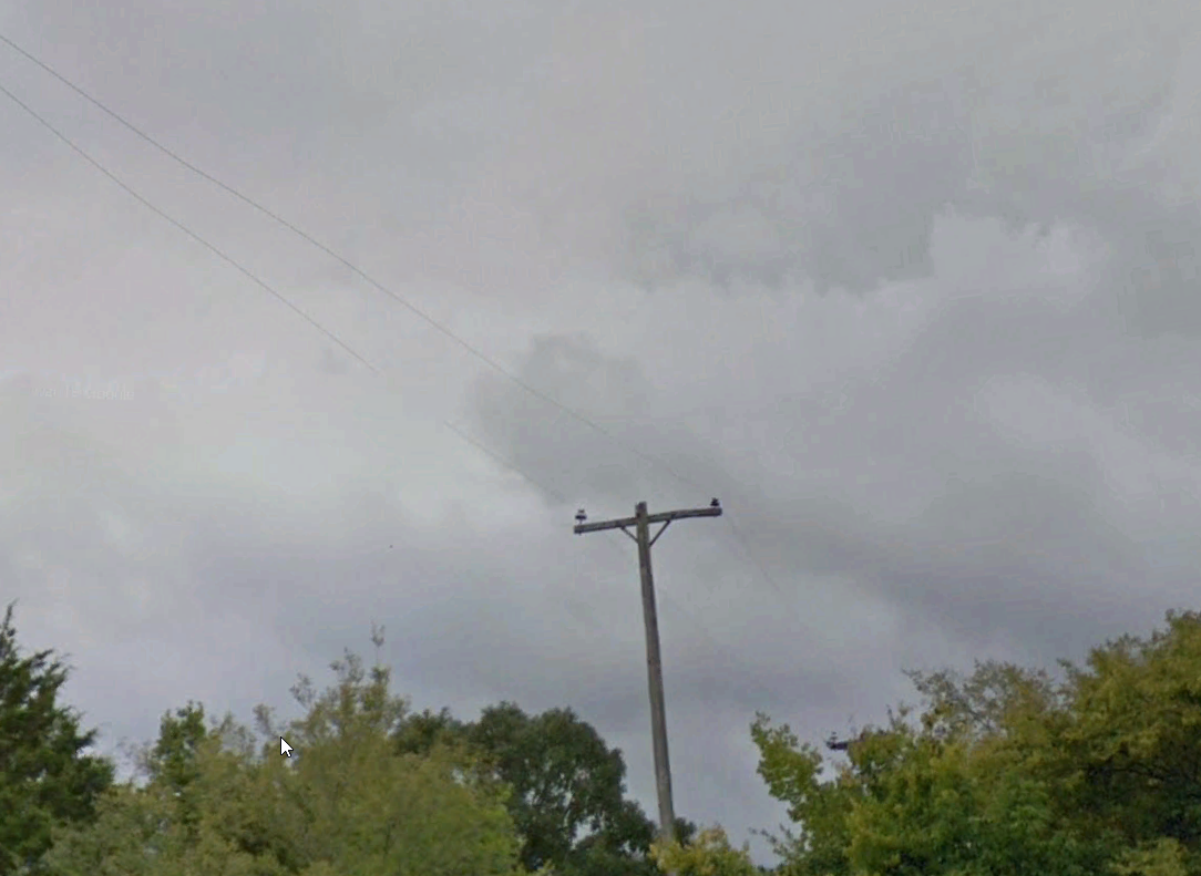
With only two wires on the pole this should be relatively easy, it is likely they would be a single phase of primary distribution and a neutral. Clues are:
No PMT, no street lighting.
But which wire is which; if you look very closely you will see that the insulator on the right is slightly smaller than the insulator on the left. The one of the left is a 25kV design, operating at 22kV, the one on the right is a 17kV design operating (nominally) at 0kV, being a neutral conductor.
Is co-location of wire classes just a US thing?
If I’m in Europe, Asia or Australia do I need to be aware of this issue? I’m afraid so, let’s see a couple of examples.
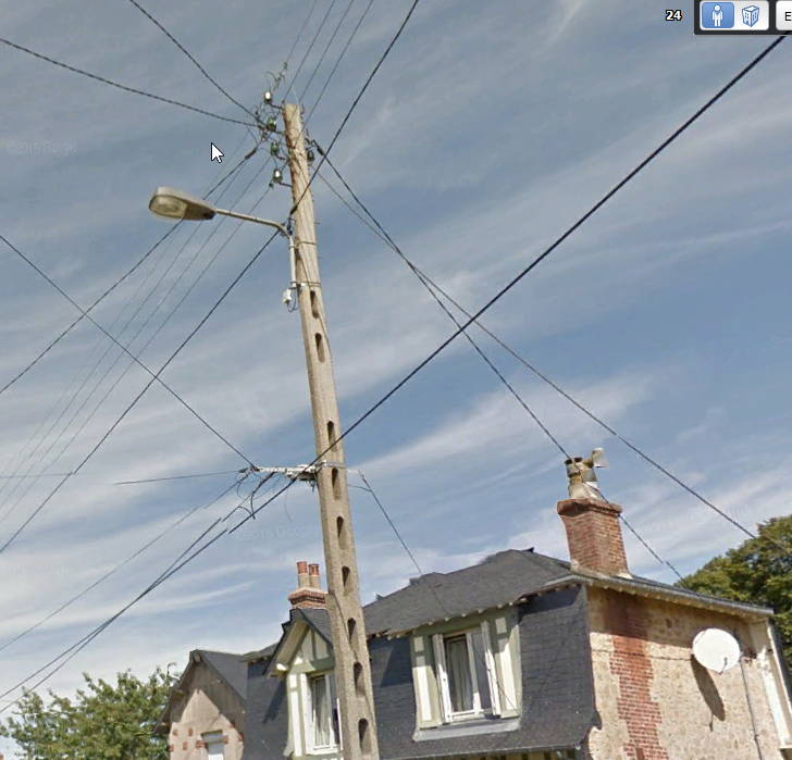
France, shows 4 wires at Primary Distribution Level, difficult to tell which the neutral, with Secondary/service below and a large gap to the telecoms wires.
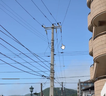
Japan, three phases of sub-transmission, over three phases of distribution, secondary/service and finally telecoms.
Conclusion
The wires on distribution networks are not always laid out precisely ‘as designed’ and there may be some disparity between layouts on ostensibly similar poles. However there are signs that you can look for which can enable you to make an accurate estimation of wire category when performing LiDAR survey works.
If you've missed any previous editions of Ask an Engineer, you can read them all here.
As Director of Engineering and heading up research and development at NM Group, Paul Richardson is a renowned power industry expert and long-time proponent of the use of 3D modeling in improving reliability and utilization, while minimizing cost. He is a chartered civil engineer (BEng Hons, CEng, MICE), and retains a wealth of experience, including more than 30 years of power line engineering.